Professional Infrastructure 3D Laser Scanning Services
A registered, state-plane-coordinated point cloud and as-built deliverable set for bridges, roadways, tunnels, and treatment plants — captured around live traffic and access constraints, without touching material testing, load rating, or subsurface utility work that belongs to other disciplines.
TL;DR: Infrastructure 3D laser scanning documents bridges, overpasses, roadways, tunnels, culverts, retaining walls, treatment plants, and utility corridors at ±5 mm registered accuracy tied to state plane control. Capture combines mobile LiDAR (NavVis VLX3, 2.56 million points per second) for walkable structures with tripod scanning for tie-in detail. Deliverables include registered point clouds in E57/RCP/RCS/LAS/PTS, Civil 3D and DWG files, cross sections, TIN surfaces, clearance reports, deviation analysis, and structural Revit models at LOD 100–500. A quote returns within 24 hours; a registered point cloud follows in 3–5 business days.
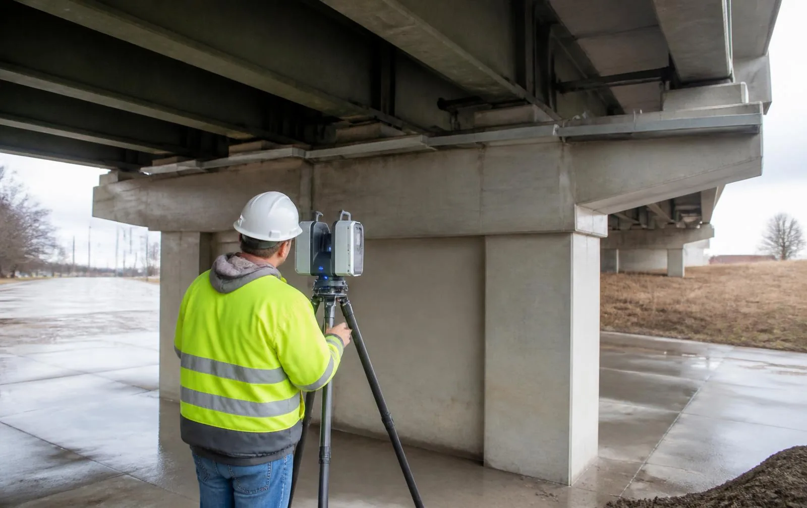
Infrastructure 3D Laser Scanning Services, explained simply
Infrastructure scanning captures the physical geometry of bridges, roads, tunnels, and treatment facilities exactly as they exist today — not as the original drawings say they should be. Mobile LiDAR walks the structure at speed while tripod scans anchor high-tolerance tie-in points, and everything ties back to a state plane control network so the result holds up in a CAD or GIS environment used by engineers on the design side.
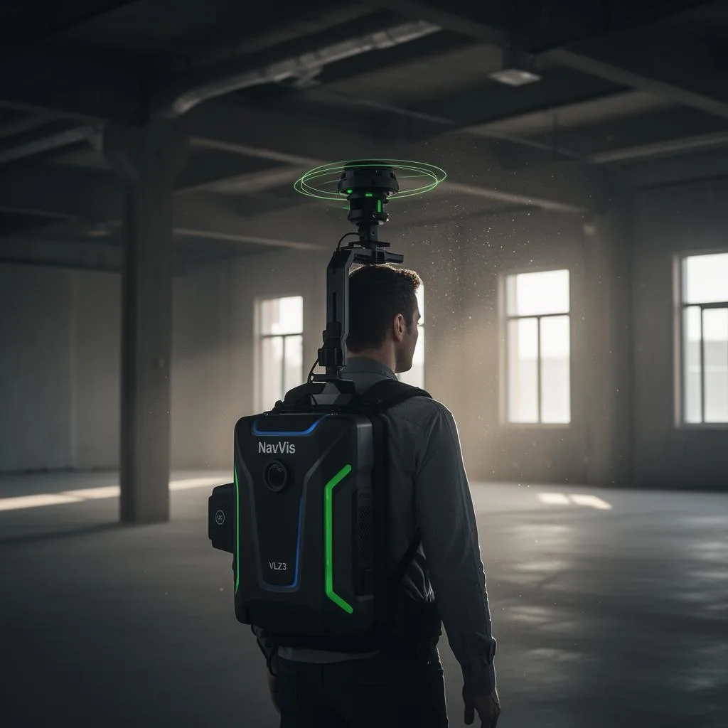
±5mm accuracy, NavVis VLX3 mobile LiDAR
Real impact on AEC project outcomes
Design from verified field conditions instead of decades-old record drawings
Answer clearance and headroom questions without a repeat site visit
Reduce lane-closure and traffic-control exposure by capturing efficiently in one pass
Get cross sections and TIN surfaces that drop directly into a civil design workflow
Flag deviations between record drawings and actual structure before design starts
Work from one control network across a corridor spanning multiple structures
From kickoff to delivery in 4 clear steps
Scope and permitting
Define the corridor or structure, coordinate lane closures, night work windows, and any permits required for confined-space or right-of-way access.
Control network
Establish and tie a control network to state plane coordinates before scanning begins, so every structure in the corridor sits on one coordinate system.
Field capture
Mobile LiDAR covers walkable decks, roadways, and tunnel bores; tripod scanning resolves abutments, bearings, connections, and other tie-in points.
Registration, QC, and deliverables
Scans are registered to control with reported residuals, then delivered as point clouds, Civil 3D/DWG files, cross sections, TIN surfaces, clearance reports, and models as scoped.
Built for teams that can't afford guesswork
- DOT and municipal engineers managing bridge and roadway inventories
- Civil engineers designing rehabilitation, widening, or replacement projects
- Structural engineers assessing existing bridges, culverts, and retaining walls
- Heavy-civil contractors planning tie-ins and staging around live infrastructure
- Utility and water/wastewater authorities documenting treatment plants and corridors
Stop losing time and money to bad data
- ✗As-built drawings that no longer match decades-old field modifications
- ✗Clearance and headroom questions that require a lane closure to answer twice
- ✗Design teams working from record drawings instead of verified conditions
- ✗Confined and hard-to-access structures that resist conventional survey
- ✗Coordination on utility corridors and substations where every foot of downtime costs money
Specific deliverables, in formats your team already uses
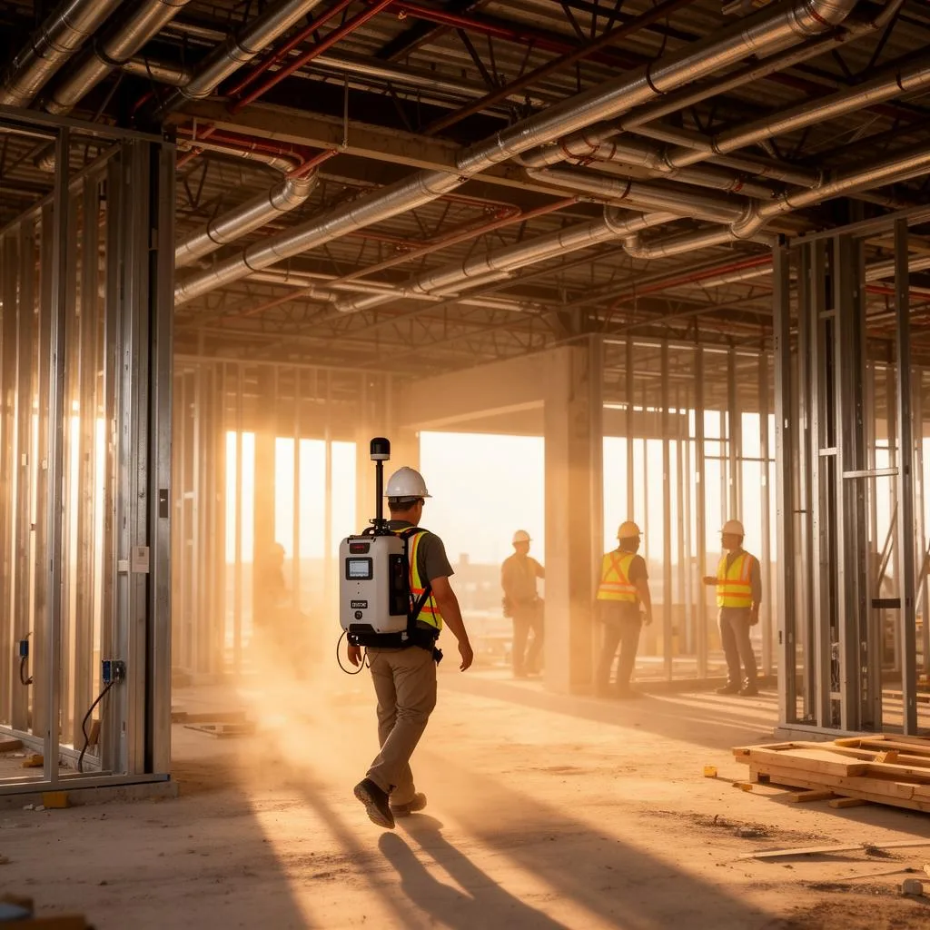
Multi-span highway overpass — verified clearances ahead of a widening design
A DOT rehabilitation program needed current geometry for a multi-span overpass and its approach roadways before a widening design could proceed, with the corridor carrying live traffic throughout the capture window and only limited night lane closures available.
Mobile LiDAR covered the deck, shoulders, and approach roadways during permitted lane closures while tripod scans resolved the abutments, bearings, and pier caps, all tied to one state plane control network. The registered model gave the design team verified clearances and cross sections built from actual field conditions rather than the original construction drawings, which had never been updated for prior deck overlays.
Infrastructure 3D Laser Scanning Services FAQ
Common questions about our 3D laser scanning services services
Complete Guide to Infrastructure 3D Laser Scanning Services
Infrastructure 3D laser scanning services document bridges, roadways, tunnels, retaining walls, water and wastewater treatment plants, and utility corridors at the accuracy engineers need to design against — not the accuracy a general contractor needs to frame a wall. For DOT and municipal engineers, civil and structural engineers, and heavy-civil contractors, the value proposition is the same across every structure type: a registered point cloud that reflects the structure exactly as it stands today, tied to state plane coordinates so it drops directly into the same coordinate system as the rest of a civil design project.
## What infrastructure scanning covers
The scope spans bridges and overpasses, roadways and intersections, tunnels and culverts, retaining walls, water and wastewater treatment plants, utility corridors and substations, and rail and dock structures. Each of these presents a different access and geometry challenge — a bridge deck is walkable and open to mobile capture, while a culvert or confined utility vault requires a static tripod setup and, often, a permit-required confined-space entry. Scoping identifies which capture method fits which portion of the structure before a crew ever mobilizes, so the field plan matches the actual access conditions rather than a generic assumption.
Capture on walkable structures — bridge decks, roadway surfaces, tunnel bores, dock platforms — is handled with mobile LiDAR, specifically the NavVis VLX3, which captures at 2.56 million points per second with four 20 MP cameras and a range up to 300m, recording 360° imagery as the operator walks the structure. This throughput is what makes it practical to cover a roadway corridor or a multi-span bridge deck in a reasonable field window instead of setting up individual tripod stations across the entire length. Tripod scanning is reserved for the detail mobile capture can't resolve cleanly: abutments, bearings, pier caps, connection details, and any tie-in point where a design team needs higher point density or a fixed, occlusion-free vantage.
Every scan, mobile or tripod, ties back to one control network established and referenced to state plane coordinates before capture begins. This matters specifically for infrastructure work because the deliverables — Civil 3D surfaces, cross sections, roadway alignments — only mean something if they sit in the same coordinate system a civil engineer's design files already use. A point cloud that isn't tied to state plane control is a disconnected model; one that is becomes a usable layer in an active design project.
## Traffic, access, and permitting constraints
Infrastructure scanning happens inside constraints that interior building scanning never faces: live traffic, permitted lane closures, night work windows, confined-space entry protocols, and right-of-way or facility-specific permits. Scope review identifies which portions of a corridor or structure can be captured during normal hours and which require a closure or a night shift, so the field plan is built around the access windows a DOT, municipality, or facility owner can actually grant rather than assuming unrestricted access. Confined spaces — utility vaults, culvert interiors, some treatment plant structures — are scanned under whatever entry protocol the space requires, coordinated with the client or facility ahead of mobilization.
None of this changes the registered accuracy of the output. A scan captured during a two-hour night lane closure ties to the same control network and holds the same ±5 mm registered accuracy as a scan captured in an unrestricted daytime window; the constraint affects field scheduling and the number of visits required, not the reliability of the geometry once it's registered.
## Deliverables built for engineering use
The core deliverable is a registered point cloud provided in E57 (open master), RCP/RCS, LAS, and PTS — usable in whatever platform a design team already runs. From that base, infrastructure projects typically add Civil 3D and DWG deliverables built specifically for roadway and corridor design workflows, cross sections cut at engineer-specified stations, and TIN surfaces for roadway, channel, or grading analysis. Clearance and headroom reports document vertical and horizontal clearances for bridges, tunnels, and overpasses — a common driver for scanning a structure in the first place, since a clearance dispute or a permit application often can't wait for a full model. Deviation analysis compares as-measured geometry against record drawings or design intent, flagging where a structure has diverged from what was originally drawn — common on infrastructure that has seen deck overlays, widening, or unrecorded field modifications over decades of service. Where a project calls for it, structural Revit models are delivered at LOD 100 through 500, with model faces typically holding ±10 mm tolerance to the registered cloud at LOD 300.
## Where scanning stops
Laser scanning captures geometry — the shape, position, and dimension of what's physically there. It does not test material condition, and a registered point cloud will not tell an engineer whether concrete has lost section, whether rebar has corroded, or whether a girder can carry a given load; that work belongs to a materials testing lab or a structural engineer performing a condition assessment or load rating, using the geometric dataset scanning produces as a starting reference rather than a substitute for it. Scanning likewise does not perform subsurface utility detection — locating buried lines and their depth is the domain of a SUE (Subsurface Utility Engineering) provider using ground-penetrating radar and utility locating equipment, a different discipline entirely from above-ground laser scanning. Being explicit about this boundary up front means a DOT engineer, structural engineer, or contractor scopes the right specialist for the right question instead of expecting a laser scan to answer something it was never built to answer.
ZEALOT Reality Capture provides infrastructure 3D laser scanning from a Powell, Ohio base and mobilizes crews to project sites in all 50 states, with travel quoted as a line item and out-of-region work scheduled as continuous trips. Field capture runs at 80,000–120,000 sq ft per field day on open roadway and corridor sections, with denser structures and confined-access zones requiring additional tripod time. A quote returns within 24 hours of scope review, a registered point cloud follows in 3–5 business days, an LOD 200 model in 10–15 business days for roughly 100,000 sq ft, and an LOD 300 model in 3–5 weeks. Pricing runs $0.05–$0.20 per sq ft, set once the corridor length, structure count, access constraints, and deliverable set are known.