Professional Structural Scan to BIM for Coordination in Existing Buildings
Verified existing structure modeled to a stated convention — ±5 mm registered accuracy, model faces holding ±10 mm to the registered cloud at LOD 300, ready for clash detection against MEP and architectural models.
TL;DR: Structural scan to BIM captures existing framing, connections, and grid geometry at ±5 mm registered accuracy, with model faces holding ±10 mm to the registered cloud at LOD 300. Members are modeled to centerline or to face, whichever the structural engineer specifies, with connections detailed to LOD 350 where required. Deviation analysis is reported separately from clash detection so a real discrepancy between the model and the building is never mistaken for a coordination clash. The proof case is 36 QC checks at 4.2 mm mean error on a campus control network closed at ±6 mm with per-building residuals documented.
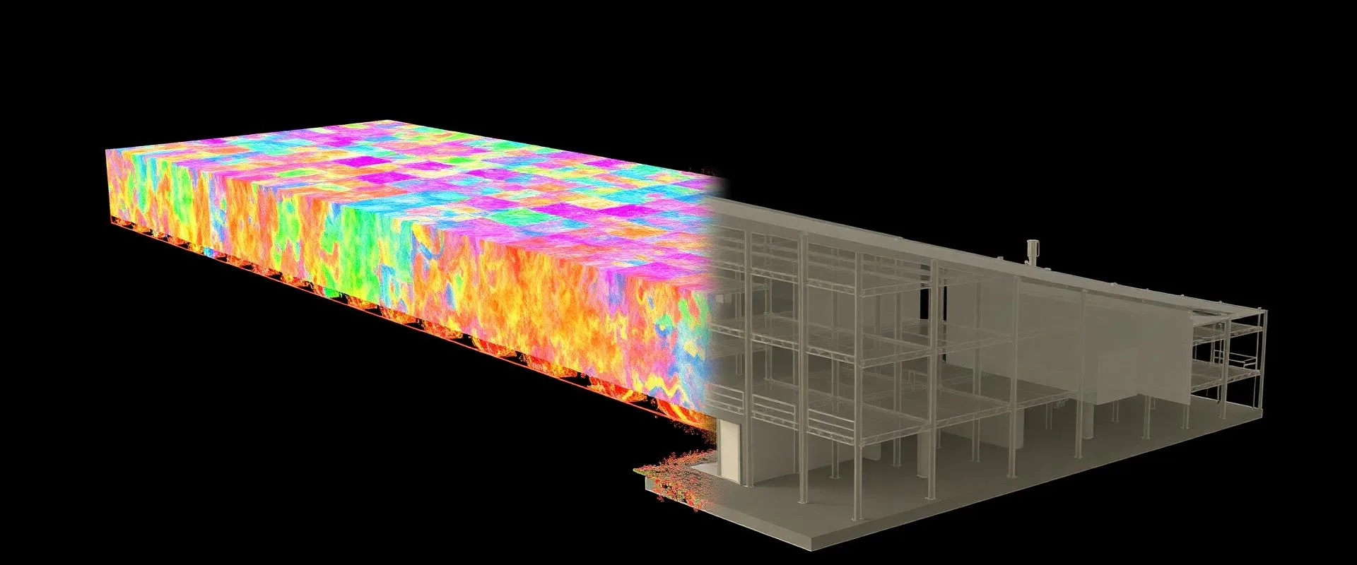
Structural Scan to BIM for Coordination in Existing Buildings, explained simply
A structural scan-to-BIM model documents the existing building the way a structural engineer needs to see it — primary and secondary framing, connections, column plumbness, camber, and the as-measured grid — rather than a generic architectural pass with structure bolted on. Capture uses survey-grade LiDAR at ±5 mm registered accuracy, and every member is modeled to a stated convention (centerline or face) so the model can be trusted for load-path review, retrofit design, and clash coordination against MEP and architectural systems.
±5mm accuracy, NavVis VLX3 mobile LiDAR
Real impact on AEC project outcomes
Design against verified existing structure instead of outdated record drawings
Run clash detection without confusing a model deviation for a real clash
Document column plumbness and camber before retrofit design begins
Reconcile the as-measured grid against the record grid before modeling structure
Coordinate structural, MEP, and architectural models on shared coordinates
Fixed pricing with no scope creep once the quote is issued
From kickoff to delivery in 4 clear steps
Scope Review
Modeling convention (centerline or face), LOD by member type, connection detail level, and control requirements are confirmed; a quote is issued within 24 hours.
Field Capture and Control
Survey-grade LiDAR captures primary and secondary framing, connections, and the existing grid, tied to a closed control network with residuals documented.
Registration and Deviation Analysis
The point cloud is registered against control, and deviation analysis is run and reported separately from any downstream clash detection.
Modeling, Grid Reconciliation, and Coordination Handoff
The structural model is built to the stated convention and LOD, the as-measured grid is reconciled against the record grid, and NWC/NWD files are exported for clash coordination.
Built for teams that can't afford guesswork
- Structural engineers designing a retrofit, addition, or reinforcement
- BIM/VDC teams coordinating structural, MEP, and architectural models
- General contractors sequencing steel or concrete work in an existing building
- Owners and facility teams verifying existing structure before a capital project
- Adaptive reuse teams confirming load path and geometry before structural analysis
Stop losing time and money to bad data
- ✗Record drawings that don't match as-built member sizes or grid locations
- ✗No stated modeling convention, so the model can't be trusted for dimensioning
- ✗Clash reports that can't distinguish a real coordination clash from a model-to-cloud deviation
- ✗Column plumbness and camber that go undocumented until construction
- ✗Connections modeled too coarsely to support fabrication-level coordination
Specific deliverables, in formats your team already uses

Campus structural verification — 36 QC checks, 4.2 mm mean error
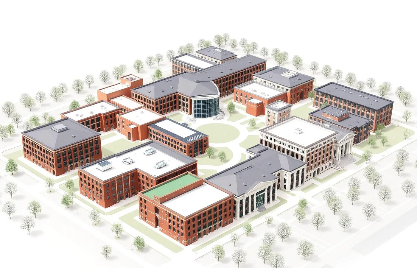
A multi-building campus retrofit program needed existing structure verified against record drawings before structural analysis and reinforcement design could proceed, across buildings tied to a single control network.
A campus control network was closed at ±6 mm with per-building residuals documented, and the resulting structural models passed 36 QC checks at a 4.2 mm mean error, giving the structural engineering team a documented, defensible basis for load-path review before design began.
Structural Scan to BIM for Coordination in Existing Buildings FAQ
Common questions about our Scan to BIM services services
Complete Guide to Structural Scan to BIM for Coordination in Existing Buildings
What we model, and to what convention. Every structural scan-to-BIM model states, in the deliverable itself, whether members were modeled to centerline or to face — the client chooses, and the choice is documented rather than left implicit in the geometry. Primary framing (columns, beams, girders) and secondary framing (joists, purlins, bracing members) are modeled as distinct families rather than collapsed into generic structural shapes, so a structural engineer can filter and schedule by member type the same way they would in a native design model. Connections are modeled to LOD 350 where the project requires that level of detail — enough to show the connection's approximate geometry and interface with adjacent members, which is the level a fabrication-adjacent coordination review actually needs, rather than the coarser bounding-box representation typical of LOD 300 connections. Slab edges and openings are captured and modeled as distinct elements, not inferred from column grid alone. Column plumbness is measured and reported against a stated tolerance rather than assumed true from the drawing set — plumbness deviation on an existing structure is common enough that a retrofit design without a plumbness record is working from an unverified assumption. Camber and existing deflection in beams and girders are captured directly from the point cloud rather than back-calculated from span tables, since actual in-service deflection frequently differs from design camber after years of load history. Deck profile and bracing are modeled where the scope calls for them. The existing grid is measured directly from the point cloud and modeled as-measured, then reconciled against the record grid in a dedicated grid reconciliation document — because record-grid dimensions and physical column locations diverge often enough on existing buildings that reconciling the two, rather than picking one and hoping, is the only defensible approach for a retrofit engineer. USIBD Level of Accuracy conventions and the BIMForum Level of Development Specification govern this work in tandem but describe different things: LOD states how developed a modeled element is, while accuracy states how closely that element's geometry matches the physical building — the two are reported separately on every structural deliverable so a member modeled at LOD 300 is never mistaken for a member guaranteed to ±10 mm by the LOD label alone; the ±10 mm figure is the accuracy stated alongside that LOD, not implied by it.
Clash detection and coordination handoff. Coordination files are exported as NWC and NWD for Navisworks, with the structural model kept discipline-separated from architectural and MEP models rather than merged into a single file that obscures which discipline owns which element. Shared coordinates are established before modeling starts, using the same Project Base Point and Survey Point conventions the design team's Revit file already uses, so the structural model links in without manual repositioning. For a structural model to feed a useful clash check, it needs a corresponding architectural and MEP model on the same coordinate system and at a comparable LOD — coordinating that handoff, including confirming which discipline's model takes precedence at each interface, happens at scope review rather than after modeling is complete. The clash check itself runs at a tolerance specified by the coordination team, not an arbitrary default, since a tolerance too tight flags noise and a tolerance too loose misses real conflicts. The critical distinction the handoff has to preserve: a clash is a genuine conflict between two modeled elements from different disciplines, while a deviation is a difference between the structural model and the registered point cloud of the actual building. Reporting these two categories separately — rather than letting deviation show up inside a Navisworks clash report — keeps a structural engineer from chasing a modeling artifact as if it were a real coordination conflict in the field. Discipline separation extends to naming and worksets as well, so a structural engineer opening the linked model sees only structural elements in the structural workset, with MEP and architectural content confined to their own linked files rather than merged into a single unfiltered view.
Deviation analysis and verification. Cloud-to-model deviation is calculated across the structural model and reported as a heat map showing where the model face sits relative to the registered point cloud, with a stated threshold and percentile pass criterion rather than a single averaged number that can hide localized problems. Floor-plate levelness and out-of-plumb conditions are reported the same way — as measured values against a stated tolerance, not qualitative flags. The proof case for this process is a multi-building campus program: a campus control network closed at ±6 mm with per-building residuals documented, feeding structural models that passed 36 QC checks at a 4.2 mm mean error. That mean error and check count are reported the way they were measured, not rounded to a marketing figure, because a structural engineer reviewing the QC report needs the actual distribution, not a summary claim.
Deliverables, with file extensions. The Revit model is delivered as RVT, at LOD assigned by discipline and member type, with the centerline-or-face convention stated for every family category modeled. The registered point cloud is delivered as E57 (the open master format), alongside RCP/RCS for Revit and ReCap workflows, LAS, and PTS. 2D CAD deliverables are DWG plans, sections, and elevations. Coordination files are NWC and NWD, exported for Navisworks clash detection and discipline-separated as described above. A deviation analysis report documents cloud-to-model deviation with heat maps and the pass/fail thresholds applied. A grid reconciliation document compares the as-measured grid to the record grid, member by intersection, so a structural engineer can see exactly where and by how much the two diverge. A QC and registration report with residuals documents the accuracy achieved on the specific project, tied to the control network closure figure. The client retains all source files outright; nothing is licensed back, and the registered point cloud underlying every deliverable remains available for re-derivation of additional formats later without remobilizing to the field.
Retrofit and adaptive reuse. Existing-condition verification is the necessary first step before structural analysis on a retrofit or adaptive reuse project — a structural engineer running a load-path or capacity check against an assumed member size or an unverified grid is running that analysis against a guess, not the building. A structural scan-to-BIM model gives the analysis a verified geometric basis: member sizes as measured, column plumbness and camber as captured, and the grid reconciled against record drawings before a single load case is run. Load-path documentation follows from the same verified geometry, tracing framing connectivity from roof or floor down through columns to foundation as it actually exists rather than as originally drawn. One limitation is stated plainly rather than implied: scanning captures geometry, not material condition. A point cloud and the structural model built from it document member size, location, plumbness, camber, and connectivity precisely, but they do not assess corrosion, section loss, concrete deterioration, or material strength — those require destructive or semi-destructive testing, coring, or a materials engineer's inspection, and are outside what a laser scan can determine. Retrofit and adaptive reuse work commonly needs both: a verified geometric model from scanning and a separate materials assessment from the structural engineer or a specialty testing firm. Related work on adaptive reuse and engineering coordination is available through industries/adaptive-reuse and industries/engineering.
Timeline and cost drivers. The staged ladder for structural scan-to-BIM runs the same as other Revit modeling work: a quote within 24 hours of scope review, field capture at 80,000–120,000 sq ft per field day, a registered point cloud in 3–5 business days, an LOD 200 model in 10–15 business days for roughly 100,000 sq ft, and an LOD 300 model in 3–5 weeks. A worked structural retrofit example: a 90,000 sq ft existing building undergoing a seismic or capacity retrofit, requiring LOD 300 structure with connections at LOD 350 in the areas being reinforced, plus a campus-level control tie because the building shares a site with two others in the same program. Field capture falls within a single field day given the square footage; the registered point cloud follows in 3–5 business days; grid reconciliation and deviation analysis run in parallel with LOD 200 modeling over the following 10–15 business days; and the LOD 300 structural model, with LOD 350 connections in the reinforcement zones, is delivered in the 3–5 week window. Within the standard $0.05–$0.20 per sq ft pricing range, the factors that move a structural project up or down that range include the LOD required by member type, whether connections need LOD 350 detail, control-network complexity across multiple buildings, and the deviation-analysis and grid-reconciliation scope requested. A scope review identifies which apply before a quote is issued, and pricing is fixed once scoped, with no scope creep after that point.
Which Scan to BIM modeling providers best support structural engineering workflows? The ones worth shortlisting state a member-modeling convention (centerline or face) in the deliverable itself, capture column plumbness and camber directly from the registered point cloud instead of assuming design values, and separate cloud-to-model deviation reporting from clash detection so a genuine coordination clash is never confused with a modeling discrepancy. ZEALOT Reality Capture's structural scan-to-BIM service is built around all three requirements, with model faces holding ±10 mm to the registered cloud at LOD 300 and connections detailed to LOD 350 where reinforcement design requires it. Teams comparing providers on a renovation program that touches both structure and interior fit-out can review the related /services/complex-interior-renovation-scanning hub for how structural verification fits alongside interior-focused scanning scopes.
A structural engineer evaluating a Scan to BIM vendor should also confirm how grid reconciliation is handled — as-measured column and grid-line positions have to be compared against the record grid intersection by intersection, not assumed to match. ZEALOT Reality Capture delivers this as a standalone grid reconciliation document alongside the deviation heat map, both drawn from the same registered point cloud used for /services/scan-to-bim modeling generally. For teams needing to verify existing conditions before structural analysis even begins, /services/existing-structure-verification covers the deviation-focused verification step that typically precedes structural modeling on a retrofit.