TL;DR
Building scanning replaces assumed record-drawing geometry with registered, ±5 mm field-accurate as-built data engineers use for capacity checks and retrofit design. Scanning captures geometry only — not material properties, embedded reinforcement, or hidden section loss — so GPR, coring, borescope inspection, and destructive testing remain necessary complements. Point clouds move through registration, verified grid, and member modeling at a stated LOD before export to structural analysis software. Cases where scanned geometry has changed the engineering answer include mislocated columns, thinner-than-recorded slabs, pre-existing deflection, and unrecorded openings.
What a structural engineer actually needs from existing-conditions data
A structural engineer performing a capacity check needs verified geometry, not a drawing set assumed to still be true. That means actual member sizes and spans, the real column grid, slab thickness and deck profile, column plumbness, existing deflection or camber, bearing conditions, and any openings, penetrations, or added loads that reduce capacity.
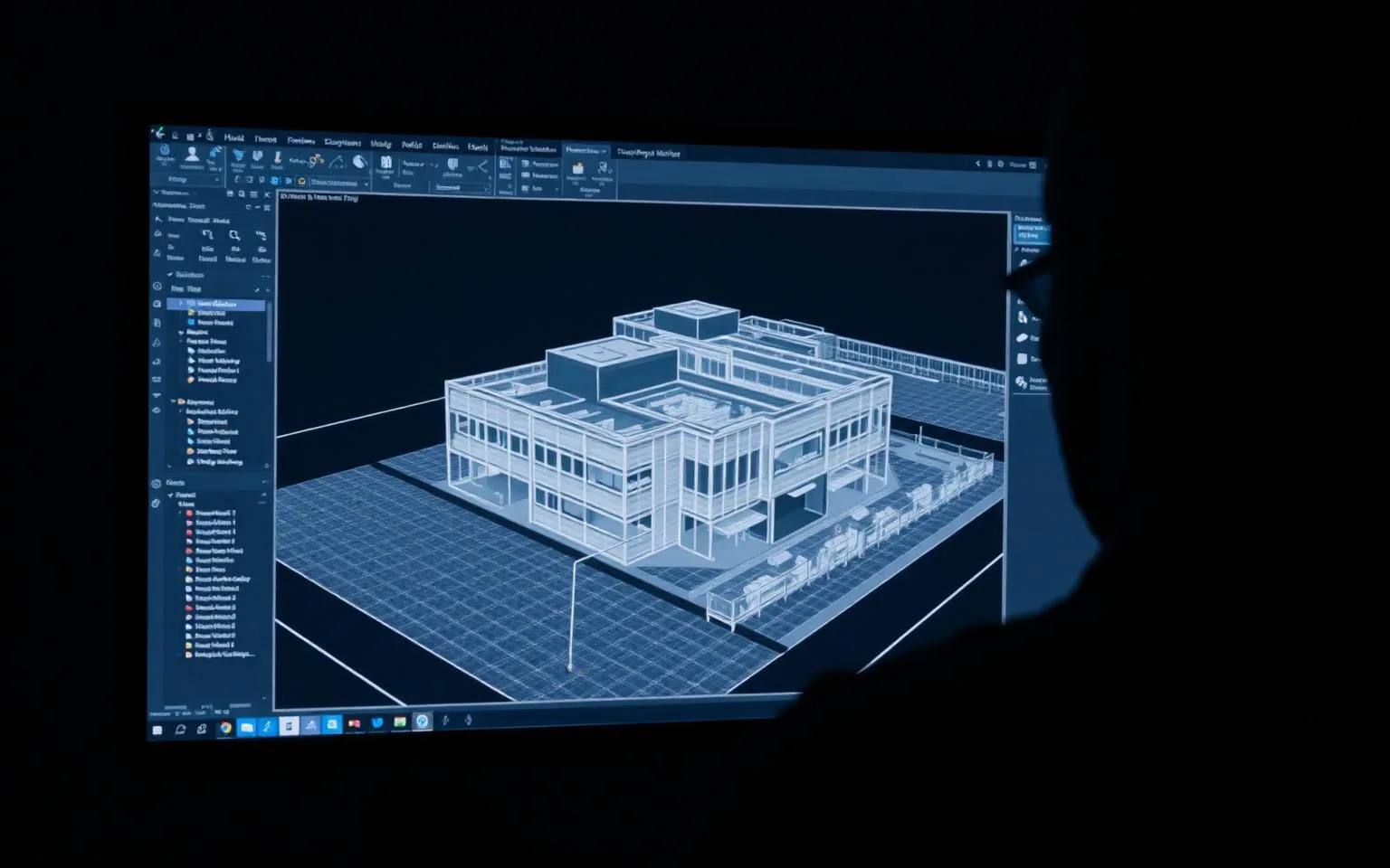
Record drawings describe design intent at the time of permitting. They do not capture what was actually built, what has moved since, or what has been altered in the decades since occupancy. Framing gets field-adjusted during construction, tenants cut openings for mechanical risers, rooftop equipment gets added without updating structural records, and slabs deflect under sustained load in ways no drawing set predicts. For a building 3D laser scanning engagement feeding a structural analysis, the gap between record drawings and physical reality is exactly the risk the scan is commissioned to close.
| Data need | Record drawings | Registered point cloud |
|---|---|---|
| Member sizes and spans | As designed | As built, measured |
| Column grid | Nominal | Actual, to ±5 mm registered accuracy |
| Slab thickness / deck profile | Specified | Measured where exposed or inferred from geometry |
| Column plumbness | Not shown | Directly measurable |
| Existing deflection/camber | Not shown | Directly measurable |
| Openings and penetrations | As originally designed | As currently exist |
| Added loads (rooftop units, added floors) | Absent if added later | Captured if visible/measurable |
Every one of these inputs feeds a load path, a member capacity check, or a deflection assessment. Verified geometry does not replace engineering judgment — it removes one entire category of uncertainty from the calculation before judgment is applied.
Many capacity checks fail not because the engineering method was wrong, but because an input to that method was assumed rather than verified. A moment calculation performed on an assumed span that is actually 150 mm shorter or longer than drawn produces a defensible-looking result built on an incorrect input. Verified geometry closes that gap at the input stage, before any calculation is run, rather than after a retrofit reveals the discrepancy in the field.
What scanning captures — and what it does not
Laser scanning captures visible geometry to a registered field accuracy of ±5 mm and models building faces to roughly ±10 mm at LOD 300. It does not measure material properties, embedded reinforcement, section loss hidden beneath cladding or finishes, or the internal condition of a connection. Engineers who need those answers still need complementary testing methods.
This distinction matters because a point cloud can look complete and still leave the questions that actually govern a retrofit decision unanswered. A scan shows where a column is, its visible cross-section, and whether it is plumb. It does not show whether that column's rebar matches the original design, whether concrete cover has carbonated, or whether a steel beam behind a fireproofing wrap has lost section to corrosion. Presenting scan data as if it answers those questions would be a disservice to the engineer relying on it — and it is the honest gap most existing-conditions marketing skips over entirely.
| Question | Answered by scanning? | Method that answers it |
|---|---|---|
| Where is the member, and what is its visible geometry? | Yes, to ±5 mm registered accuracy | Laser scanning |
| Is the column plumb, and is there existing deflection? | Yes | Laser scanning |
| What is embedded reinforcement layout? | No | Ground-penetrating radar (GPR) |
| What is the material strength / composition? | No | Coring, lab testing |
| Is there hidden section loss behind cladding or fireproofing? | No | Borescope inspection, selective demolition |
| Is a connection detail actually as drawn? | No | Destructive testing, selective opening |
GPR locates embedded rebar and post-tensioning cable without opening the slab. Coring extracts physical samples for compressive strength testing. Borescope inspection lets an engineer see inside a cavity through a small access hole. Destructive testing — selectively opening a connection or removing a section of finish — is still the only way to verify hidden detail with certainty. Scanning and these methods are not competitors; a competent existing-conditions program uses scanning to establish geometry everywhere, then targets GPR, coring, borescope, or destructive testing at the specific locations where the engineer needs material or hidden-condition answers.
A well-run existing-conditions program treats this honesty as a scoping decision rather than a disclaimer buried in a report appendix. Before capture begins, the engineer and the scanning provider should agree on which elements need only geometric verification and which elements are candidates for targeted GPR, coring, or borescope work based on visible condition, age, exposure history, or known problem areas flagged during a walkthrough. Sequencing it this way — geometry first, targeted destructive or semi-destructive testing second, at locations the geometry review identifies as worth investigating — keeps the more expensive testing methods focused rather than blanket-applied across a building where most of it is unnecessary.
From point cloud to structural model
The workflow runs from a registered point cloud, to a verified grid, to member modeling at a stated convention, to export into structural analysis software. Each step needs to be specified before scanning starts, because the engineer's downstream model depends on decisions made at capture and modeling time, not decisions made after the fact.
Field capture — typically with a static scanner such as the Leica RTC360 for structural elements and a mobile system like the NavVis VLX3 (2.56 million points/sec) for large walkable areas — produces overlapping scans that are registered into one coordinate system, closed against a campus control network at ±6 mm in typical practice. From that registered cloud, a verified grid is established against actual column locations rather than assumed drawing coordinates. Members are then modeled to a stated Level of Development, commonly LOD 200–350 depending on the analysis need, and to a stated convention — centerline or face of member — because that single decision changes every span length and load calculation downstream.
| Workflow step | What the engineer specifies | Why it matters |
|---|---|---|
| Field capture | Instrument, control tie-in, coverage | Determines achievable accuracy and completeness |
| Registration | Accuracy tolerance, confidence level | Sets the ceiling on every downstream measurement |
| Grid verification | Tolerance against control | Confirms the model's coordinate system matches the field |
| Member modeling | LOD by element, centerline vs face | Directly changes span, section, and load-path values in the analysis model |
| Export | File format, analysis software target | Determines whether the model is usable without rework |
A model exported without these specifications stated up front routinely requires rework once the analysis software returns implausible results — usually because the modeling convention did not match what the engineer assumed. Coordinating this scope with as-built documentation standards before capture begins avoids that rework.
Quality control on the registered cloud itself is part of this workflow, not a separate step. A structural deliverable should be checked against control at multiple points across the building rather than accepted on the strength of the registration software's internal report alone. Programs that run a defined set of QC checks — for example, 36 checks closing at a 4.2 mm mean error across a project — give the engineer a documented basis for trusting the geometry before it becomes an input to a capacity check, rather than discovering a registration problem after the analysis model is already built.
Where it changes the answer
Verified geometry changes structural conclusions often enough that assuming record drawings are correct is itself a risk. Documented patterns include a column not located where drawings show it, a slab measured thinner than its record thickness, a beam already deflected before new load is added, and an opening cut into a member after original construction with no as-built update.
These are not hypothetical categories. On a 220,000 sq ft industrial plant, a scan-based as-built review found 143 pipe runs routed differently than the PDFs on file showed — a mismatch discovered only because the physical space was measured rather than assumed. The same phenomenon applies directly to structure: a column shifted from its drawn grid line changes an eccentricity calculation; a slab measured thinner than specified changes a punching-shear check; a beam already carrying visible deflection before a new rooftop unit is added changes the available capacity for that addition.
| Scenario | What record drawings show | What verified geometry reveals | Structural consequence |
|---|---|---|---|
| Column location | On grid | Offset from grid | Changed eccentricity, revised capacity check |
| Slab thickness | Design thickness | Thinner as-built section | Revised punching-shear or deflection check |
| Beam condition | Level, undeflected | Existing camber or sag | Reduced remaining capacity for added load |
| Opening | Not present or as-designed | Cut post-construction | Reduced member capacity, possible reinforcement needed |
An engineer proceeding on record-drawing geometry alone inherits every one of these discrepancies as unrecognized risk. A verified model surfaces them before the analysis is run, not after a retrofit is underway.
The consequence is rarely limited to the specific member found out of tolerance. A column offset from its drawn grid line changes the eccentricity calculation for that column, but it can also change the tributary area and load path assumed for adjacent members, meaning one discrepancy discovered in the field can propagate through several capacity checks that were built on the original grid assumption. This is why grid verification early in the workflow — not member-by-member spot checks late in the process — is the more defensible sequence for a retrofit or addition project.
Accuracy needed for structural assessment
Structural existing-conditions work does not need the tightest achievable accuracy for every element — it needs accuracy matched to the decision the geometry supports. USIBD Level of Accuracy (LOA) bands map cleanly onto structural use cases, and specifying beyond what a use case requires adds cost without adding usable information.
| USIBD LOA band | Typical structural use case | Overkill for |
|---|---|---|
| LOA 10–20 | Early feasibility, gross massing | Any capacity check |
| LOA 30 | Preliminary retrofit planning, existing grid confirmation | Connection-level design |
| LOA 40 (≈±5 mm registered, ±10 mm at LOD 300 faces) | Member capacity checks, load-path verification, deflection assessment | Feasibility-only studies |
| LOA 50 | Fabrication-level connection design, tight-tolerance retrofit | Most existing-building capacity checks |
Most structural capacity checks are well served by the LOA 40 band — the ±5 mm registered field accuracy and ±10 mm modeled-face tolerance at LOD 300 that scanning providers commonly deliver for existing-conditions work. Specifying LOA 50 across an entire building for a capacity check that only needs LOA 40 adds field time and cost without changing the engineering conclusion; that level is better reserved for the specific connections or members where fabrication-level tolerance is actually the deliverable. Coordinating LOA selection with the engineering team's actual analysis need — rather than defaulting to the tightest number available — keeps the scope proportionate to the decision it supports.
Coordinating LOA selection with the engineering team's actual analysis need — rather than defaulting to the tightest number available — keeps the scope proportionate to the decision it supports.
Cost is also part of this proportionality decision. Existing-conditions scanning for structural and MEP scopes commonly runs $0.05–$0.20 per sq ft depending on building complexity, access, and required LOD, with most engineering-focused structural assessments — typically 80,000–120,000 sq ft — falling toward the middle of that range once LOA 40 accuracy and LOD 300 member modeling are specified. Pushing every element to LOA 50 pricing across a full building is rarely justified when only a handful of connections require that tolerance; scoping the tighter tier to those specific locations keeps the project's cost proportionate to the decision the data supports.
For teams building out the survey standard across multiple projects, the companion guides on building scanning for existing conditions and structural retrofit scan-to-BIM standards cover LOA selection and modeling conventions in more depth. Questions on a specific project can be directed to 614-210-3679.