TL;DR
TL;DR: As-built accuracy depends on instrument accuracy, control-network registration, and modeling tolerance working together; renovation teams that specify ±5mm registered field accuracy and verify it with a documented control network and deviation checks avoid the coordination failures caused by inaccurate as-built documentation.
Table of contents
- What "accuracy" actually means
- Instrument accuracy vs registration accuracy
- Absolute accuracy vs relative accuracy
- Choosing an accuracy target for project risk
- Control networks and how registration is verified
- Field workflow that protects accuracy
- Deviation checks against the point cloud
- What an accuracy or registration report should contain
- How accuracy shows up in cost and schedule
- Common ways accuracy is quietly lost
- FAQ
What "accuracy" actually means
"Accuracy" is used loosely on renovation projects, and that looseness is where disputes start. A single number rarely describes the whole chain from field capture to a construction document. Accuracy has to be tracked at four distinct points:
- Instrument accuracy — the manufacturer-rated precision of the scanning hardware itself.
- Registration accuracy — how well individual scans align to each other and to a shared coordinate system.
- Modeling tolerance — how faithfully the Revit or CAD geometry represents the point cloud once elements are drawn.
- Drawing tolerance — the accuracy implied by how a 2D deliverable is dimensioned and annotated.
Errors compound down this chain. A scanner with excellent instrument accuracy can still produce a poor as-built if registration drifts, and a well-registered point cloud can still yield an inaccurate model if elements are modeled to design intent rather than to measured geometry. Renovation teams evaluating a proposal or dataset should ask which of these four accuracy is being quoted for, not just "how accurate is it."
Instrument accuracy vs registration accuracy
Instrument accuracy is a hardware spec: the deviation a single scan will show under ideal conditions, based on beam divergence, ranging error, and angular resolution. It is necessary but not sufficient. On any building larger than a single room, multiple scan setups must be merged, and the accuracy of that merge — registration accuracy — determines the accuracy of the finished dataset far more than the instrument spec does.
Registration accuracy is reported as a root-mean-square (RMS) error across overlapping scans or against control points. A platform like the NavVis VLX3, capturing at 2.56 million points per second with 4 x 20 MP cameras and up to 300m range, still depends on a disciplined registration workflow to hold ±5mm registered field accuracy across a full floor plate. The hardware sets the ceiling; the field and registration workflow determine whether that ceiling is reached. See the deeper discussion of this distinction in what ±5mm accuracy actually means.
Absolute accuracy vs relative accuracy
Two datasets can both look accurate and still fail different checks:
- Relative (local) accuracy measures internal consistency — the distance between two points inside the scan compared to their true physical distance. This is what matters for fabricating a duct run or checking wall parallelism within a single space.
- Absolute accuracy measures how well the entire dataset aligns to real-world survey coordinates or a site control network. This is what matters when a renovation model has to align with civil drawings, adjacent building surveys, or GPS-tied coordinates.
A point cloud with strong relative accuracy but no absolute tie-in is unsuitable for site-wide coordination even if every room measures correctly. Renovation scopes that touch building envelope, additions, or multi-building campuses should require absolute accuracy tied to survey control, not just internally consistent relative accuracy.
Choosing an accuracy target for project risk
Accuracy targets should be set by the cost of being wrong, not by default habit. A tighter target adds field time and QC effort; a looser target is fine where tolerances are generous or fieldwork will re-verify dimensions anyway.
| Accuracy class | Typical target | Best-fit use case |
|---|---|---|
| Reference / planning | Relative geometry only, no registered accuracy claim | Feasibility studies, marketing renderings, early massing |
| Standard as-built | ±5mm registered field accuracy, ±10mm typical model tolerance at LOD 300 | Interior renovation, tenant fit-out, MEP coordination |
| Structural / tie-in critical | ±5mm registered field accuracy with tighter modeling QC and denser deviation sampling | Structural retrofit, new-to-existing structural connections, historic structural assessment |
| Fabrication-grade | ±5mm field accuracy verified against physical field checks | Prefabricated MEP assemblies tying into existing structure |
Structural renovation work benefits from a documented tolerance chain; see scan-to-BIM tolerance analysis for engineers and structural scan-to-BIM services for how tolerance budgets are built for load-bearing work.
Control networks and how registration is verified
An independent control network is the single most important safeguard against inaccurate as-built documentation. Without it, a point cloud can be internally well-registered and still be positioned incorrectly relative to the real building or site.
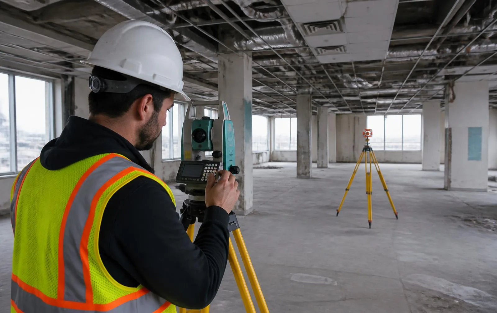
A control network typically consists of surveyed targets or total station points established independently of the scanner, then used to check — not just to assist — registration. Verification follows a defined workflow:
- Establish control points using a total station or GNSS survey independent of the laser scanner.
- Register individual scans into a unified point cloud using cloud-to-cloud or target-based registration.
- Compare registered scan positions against the independent control points and compute RMS error.
- Flag any control point residual exceeding the project's accuracy target for re-scan or re-registration.
- Document final RMS error and control point residuals in the registration report.
This workflow is what separates a defensible as-built from an unverifiable one. Full building scanning engagements should specify this control step explicitly in the scope; see building 3D laser scanning and 3D laser scanning scope of work for how this is written into a contract.
Field workflow that protects accuracy
Accuracy is largely won or lost in the field, before any modeling happens. A field workflow that protects accuracy typically includes:
- Walk the site and place control targets before scanning begins, ensuring adequate overlap and line-of-sight between setups.
- Capture with sufficient scan density and overlap to avoid relying on a single weak registration path between distant areas of the building.
- Use 360° coverage with panoramas every 2–3 meters to maintain visual reference for later QC and to catch occlusions immediately.
- Re-scan or add setups on the spot when an area is occluded by furniture, ductwork, or active construction rather than accepting a gap.
- Confirm registration quality in the field, on the day of capture, so gaps or drift are corrected before the crew leaves site.
Most sites are captured in 1–3 days at a throughput of roughly 80,000–120,000 sq ft per field day, with the first deliverable available within 48 hours. That schedule only holds if the field crew is verifying registration as they go rather than deferring it to the office. Coordination-heavy renovation projects should review as-built documentation services and point cloud services for how field QC is structured into the deliverable.
Deviation checks against the point cloud
Once a model exists, the only reliable check on modeling accuracy is comparing the modeled geometry back against the source point cloud — not against the drawings that were used to build it. Deviation analysis (sometimes called cloud-to-mesh or cloud-to-BIM comparison) overlays the model on the registered scan and flags elements that fall outside the modeling tolerance.
This check catches problems that visual review misses: a wall modeled straight where the point cloud shows a bow, a floor slab modeled level where the cloud shows slope, or a beam offset from its as-scanned position because it was snapped to a grid line. Renovation teams relying on scan-to-BIM output for design coordination should require a deviation report as a deliverable, not just a finished model. See point cloud QA in scan-to-BIM and as-built accuracy and design coordination for how this check integrates with design review.
What an accuracy or registration report should contain
A registration and accuracy report is the artifact that makes accuracy claims verifiable rather than asserted. At minimum it should include:
- The control network used, including number and distribution of control points across the site.
- Registration RMS error, both scan-to-scan and against control points.
- Any areas with known limitations — occlusions, reduced density, or setups excluded from registration.
- The instrument and settings used, tied to the manufacturer's stated instrument accuracy.
- Modeling tolerance applied during scan-to-BIM conversion, and the LOD level modeled (LOD 200, LOD 300, LOD 400, or a mixed LOD 200–400 scope).
- Deviation analysis results for modeled elements against the point cloud, where modeling was performed.
Without this report, "the scan is accurate" is a claim with no way to check it. Requesting this report should be standard practice on any renovation project using scan-to-BIM or existing structure verification deliverables.
How accuracy shows up in cost and schedule
Accuracy is not free, and it is not infinite either — past a certain point, tighter accuracy adds cost without adding usable value. The cost drivers are field time (denser scan setups, control surveying), QC time (deviation checks, registration verification), and modeling time (holding tighter tolerance during element creation). Scanning cost for typical projects runs $0.05–$0.20/sq ft, with the higher end reflecting denser capture, control surveying, or occupied/occluded conditions that slow the field crew.
Schedule impact shows up mainly in field days and QC turnaround, not in the scanning technology itself. A project that skips control surveying to save a day in the field often loses more time later reconciling coordination clashes discovered during construction. For a fuller cost breakdown, see how much does 3D laser scanning cost.
Common ways accuracy is quietly lost
Accuracy failures rarely announce themselves. The table below pairs the failure mode with the specific check that catches it before it reaches construction documents.
| Failure mode | Check that catches it |
|---|---|
| No independent control network; registration drifts across a large floor plate | Compare registered scan positions to independent survey control and review RMS error |
| Occluded areas scanned with a single pass, leaving gaps filled by assumption | Review panorama coverage and flag areas without 360° overlap during field QC |
| Modeler draws elements to design intent instead of measured geometry | Run deviation analysis of modeled elements against the source point cloud |
| Registration report never produced or reviewed | Require a registration and accuracy report as a contract deliverable, not an optional extra |
| Point cloud in the wrong file format loses precision or metadata in translation | Confirm delivery in a lossless format (E57, RCP, RCS, LAS, PTS) and verify against source |
| Relative accuracy assumed to be sufficient for site-wide or multi-building coordination | Confirm absolute accuracy against control before using the model for site-wide alignment |
File format handling is a frequent, avoidable source of degraded accuracy; see point cloud file formats: E57, RCP, LAS, PTS for how translation between formats can introduce error if not verified. Organizing multi-building or multi-phase datasets is covered in organizing point cloud data for scan-to-BIM.
Renovation and adaptive reuse work carries more accuracy risk than new construction because existing conditions are irregular by nature — out-of-plumb walls, undocumented structural changes, buried MEP routing. Due diligence scopes should build accuracy verification in from the start rather than treating it as a post-delivery audit; see adaptive reuse due diligence guide and adaptive reuse for how this plays out across a renovation program.
FAQ
What is a reasonable as-built accuracy target for a renovation project?
Most renovation and adaptive reuse projects specify ±5mm registered field accuracy for the point cloud and ±10mm typical model tolerance at LOD 300. Tighter tolerances are reserved for structural retrofits or mechanical tie-ins where clash risk is high.
What is the difference between absolute and relative accuracy?
Absolute accuracy measures how closely the point cloud aligns with real-world survey coordinates. Relative (local) accuracy measures how consistent dimensions are within the scan itself, such as wall-to-wall distances. A model can have excellent relative accuracy but poor absolute accuracy if it was never tied to control.
How is registration accuracy verified?
Registration accuracy is verified by comparing scan-to-scan overlap error and checking scan positions against an independent control network of surveyed targets or total station points, then reporting root-mean-square error against those control points.
What causes inaccurate as-built documentation on renovation projects?
Common causes include skipping an independent control network, over-relying on cloud-to-cloud registration without check points, scanning through occlusions without validation, and letting modelers snap geometry to design intent instead of the measured point cloud.
Should an accuracy report be requested as a deliverable?
Yes. A registration and accuracy report documenting control point residuals, registration error, and any known limitations should accompany every as-built dataset used for renovation design or construction documentation.