TL;DR
Scan to BIM accuracy failures in MEP systems stem from unique challenges like dense pipe racks causing data gaps (occlusion), insulation obscuring true pipe diameters, and reflective ductwork creating noise. These data issues lead to modeling errors, causing design clashes, incorrect material orders, and costly rework during construction.
Scan-to-BIM accuracy failures in Mechanical, Electrical, and Plumbing (MEP) systems are most often caused by data gaps from occlusion, misinterpretation of insulated elements, and point cloud noise from reflective surfaces. These raw data problems lead to critical modeling errors, such as incorrect pipe sizes or locations, which can derail design, procurement, and fabrication for a renovation project. Understanding the source of these failures is the first step toward preventing them.
Of all disciplines, MEP is the most challenging for creating an accurate as-built model from point cloud data. The inherent complexity and density of these systems create unique problems that are less common when modeling architectural or structural elements.
Why MEP Is the Hardest Discipline to Model
Modeling MEP systems requires a significant amount of interpretation by the BIM technician, as the point cloud rarely provides a perfect, complete picture. The environment itself works against a clean capture. Key challenges include extreme occlusion, reflective surfaces, and access limitations.
Occlusion and Data Gaps
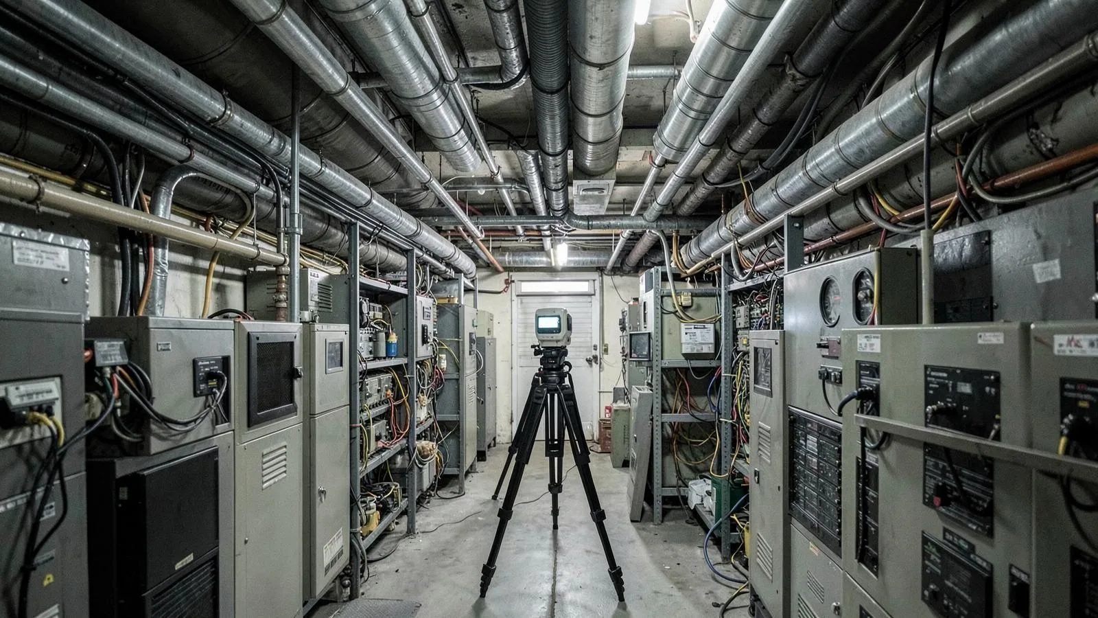
Mechanical rooms, ceiling plenums, and utility corridors are packed with overlapping pipes, conduit, and ductwork. Each element casts a "shadow" in the laser scan data, blocking the scanner's view of whatever is behind it. This is known as occlusion. To build a complete picture, a scanning provider must place the scanner in dozens or even hundreds of positions to see around these obstructions. Even with a dense scan plan, some elements will remain partially or completely obscured, forcing the modeler to make educated guesses to connect the visible segments.
Insulation vs. True Pipe Diameter
Pipes and ducts are often wrapped in insulation of varying thickness. A laser scanner captures the outer surface of this insulation, not the actual outer diameter (OD) of the pipe or duct itself. An inexperienced modeler might simply trace the surface they see in the cloud, resulting in a model where a 4-inch pipe is incorrectly modeled as a 6-inch pipe. This single error can trigger false clash reports and lead to the purchase of incorrect fittings and supports. A skilled technician must identify insulation and apply standard component sizes.
Reflective Surfaces and Data Noise
New or clean metallic surfaces, like stainless steel conduit, aluminum-jacketed insulation, and galvanized steel ductwork, are highly reflective. These surfaces can scatter the laser beam, creating "noise" or phantom points in the data that can obscure real geometry. This requires more intensive point cloud cleanup and careful interpretation to distinguish between an actual object and a reflection.
Access and Safety
Effectively scanning MEP systems often means accessing tight, difficult-to-reach spaces. Setting up a terrestrial scanner in a cramped ceiling plenum or on top of equipment is time-consuming and sometimes impossible. This is an area where combining terrestrial scans with data from a mobile mapping system like the NavVis VLX can help fill in gaps and improve overall coverage without extensive setup time. For a deeper look at different capture methods, see this comparison of mobile vs. terrestrial laser scanning.
Common MEP Scan-to-BIM Failures and Their Impact
When data issues are not properly managed during capture and modeling, they result in specific failures within the Revit model. These inaccuracies directly affect design decisions and can lead to significant downstream problems during construction. A poor point cloud is one of the biggest warning signs for Scan-to-BIM projects.
| Failure Type | Common Cause(s) | Downstream Project Impact |
|---|---|---|
| Incorrect Pipe/Duct Sizing | Modeling to insulation OD; using non-standard sizes. | False clashes, incorrect fitting/valve orders, wasted material, prefabrication errors. |
| Incorrect System Routing | Occlusion forcing modeler to guess path between visible points. | New design clashes with existing systems, requiring costly on-site rerouting and change orders. |
| Missed Components | Insufficient scan density; occlusion hiding valves, dampers, junction boxes. | Designs fail to account for tie-in points, access requirements, or existing devices, leading to rework. |
| Inaccurate Slopes/Elevations | Poor scan registration; modeler not enforcing system requirements. | Gravity-fed systems (e.g., sanitary) are modeled incorrectly, causing coordination failures with new designs. |
| Clearance Clashes | Low-density point cloud; model not checked against cloud. | New equipment cannot be installed, or code-required maintenance clearances are violated. |
These failures undermine the primary purpose of Scan-to-BIM: creating a reliable digital twin for clash-free design. The consequences range from minor design adjustments to major budget overruns and schedule delays.
Best Practices for Preventing MEP Accuracy Failures
Preventing these errors requires diligence in both the field capture and the BIM modeling phases. A robust quality assurance process is essential.
During Field Capture
- High-Density Scanning: Specify higher scan densities and resolutions in complex areas like mechanical rooms and above ceilings. This ensures smaller elements like conduits and valves are captured.
- Strategic Scan Locations: The field team must be experienced in identifying and mitigating occlusion by adding more scanner setups to "see" around obstructions.
- Clear Scope of Work: The project scope of work must clearly define what needs to be modeled and to what Level of Detail (LOD), ensuring capture teams focus on the right elements.
- Combined Technology: Use a mix of terrestrial and mobile scanning to balance high accuracy in critical areas with comprehensive coverage in more open spaces.
During Modeling and QA
- Experienced Technicians: The team modeling the MEP systems must have domain knowledge to recognize insulation, apply standard pipe sizes, and correctly interpret ambiguous data. This is a key service for MEP renovation projects.
- Rigorous QA Process: Every modeled element must be checked against the point cloud. A formal Scan-to-BIM QA process uses deviation analysis to confirm that model faces are within the agreed-upon tolerance of the point cloud data, typically ±10 mm at LOD 300.
- Define Tolerances Early: The project team must agree on acceptable tolerances for the model. These tolerances directly influence how clash detection is performed and what constitutes a "real" issue.
- Use Point Cloud for Verification: The point cloud should not be discarded after modeling. It remains the ground truth and should be used by the design team to visually verify conditions in areas of uncertainty. Performing quality checks before modeling begins is also critical to success. For more, see this guide to point cloud QA checks before Scan-to-BIM.
By implementing these practices, project teams can significantly reduce the risk of MEP accuracy failures and leverage Scan-to-BIM to its full potential for de-risking complex renovation projects.
Next step
To ensure your next MEP renovation is based on reliable as-built data, discuss your project requirements with an experienced reality capture team. Contact ZEALOT Reality Capture for a quote within 24 hours.
Next step
Scope review and a written quote come back within 24 hours. Call 614-210-3679 or send project details through the contact page.