TL;DR
Most of a building's mechanical, electrical, and plumbing systems live where nobody can see them — above ceilings, inside chases, through mechanical rooms. MEP scanning documents those spaces through planned ceiling-tile lifts and dense targeted capture, delivering mains, laterals, VAVs, sprinkler runs, and cable trays at ±5mm accuracy and modeled at LOD 200–300 by discipline. Above-ceiling capture adds modest field time and eliminates the return visits that plague coordination projects starting from guesswork.
Most of a building's mechanical, electrical, and plumbing systems live where nobody can see them — above ceilings, inside chases, through mechanical rooms. MEP scanning documents those spaces through planned ceiling-tile lifts and dense targeted capture, delivering mains, laterals, VAVs, sprinkler runs, and cable trays at ±5mm accuracy and modeled at LOD 200–300 by discipline. Above-ceiling capture adds modest field time and eliminates the return visits that plague coordination projects starting from guesswork.
How do you scan above a ceiling without opening the whole thing?
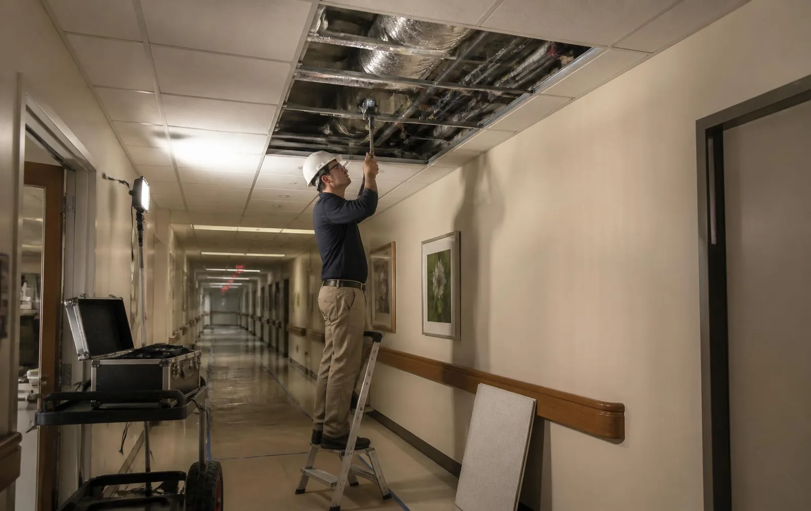
Opening every ceiling tile in a building is neither necessary nor welcome — especially somewhere occupied. Instead, a capture plan targets tile lifts along mains and at key intersections. Fast static scans through each opening capture the visible geometry, and that anchor data drives modeling of main-versus-lateral routing across the *entire* plenum — not just the small area physically opened. A limited number of strategic openings can document a much larger ceiling void.
What actually gets captured and modeled?
| System | Typical LOD |
|---|---|
| Supply and return ductwork | 200 (routing/clearance) or 300 (tie-in geometry) |
| Hydronic and sanitary piping | 200–300 depending on scope |
| Conduit and cable tray | 200–300 |
| Sprinkler mains and laterals | 200–300 |
| VAV boxes and terminal units | 300, when precisely located |
LOD 200 is the right call when a system just needs to be known and routed around. LOD 300 is for anything being tied into, relocated, or replaced — where precise geometry is what design and fabrication actually depend on.
A real project: 14 tiles, 38,000 sq ft of plenum
A med-surg renovation inside an active hospital wing needed real plenum conditions, but facilities would only pre-clear 14 ceiling tiles across 5 zones — this was occupied space, and opening more wasn't an option. Targeted static scans through exactly those 14 openings anchored modeling of mains versus laterals across the entire wing. The resulting federated model correctly placed VAVs, sprinkler runs, and med-gas routing across 38,000 sq ft of ceiling — and headed off 23 RFIs before they could happen, with the plenum physically opened only 14 times in the whole project.
Why does this matter for prefabrication specifically?
Spool drawings and rack assemblies built against *scanned* tie-in geometry fit the building the first time, because the model matches reality rather than an assumption. Misfit prefab — a rack or spool that doesn't land where the drawing said it would — means refabrication, extra crane time, and schedule loss, all avoidable with the same few hours of targeted scanning that made the hospital project above come in clean.
What problems does above-ceiling scanning actually solve?
- Coordination models missing real existing systems — replaced with measured geometry
- Clashes discovered during installation, not design — moved back to the model, where they're cheap to fix
- Prefab spools and racks that don't fit — built against real tie-in geometry instead
- Ceiling plenums more congested than anyone realized — documented before design commits to a route
- Repeated tile-lifting site walks for every trade — one capture serves every discipline
Who commissions MEP scanning?
- MEP engineers designing replacements and tie-ins against measured reality
- Mechanical and electrical subs planning prefab that has to fit the first time
- VDC teams running clash detection against real existing conditions, not guesses
- GCs coordinating congested ceiling space across multiple trades
- Facility teams documenting what maintenance inherited with no record
What kind of buildings actually need this, beyond hospitals?
Occupied-facility protocols like the tile-lift approach above were proven in hospitals specifically because that's where the access constraints are tightest — but the same targeted-capture logic applies anywhere ceiling space matters and disruption has to stay minimal: schools running normal class schedules, occupied office buildings mid-lease, and mechanical rooms in any building type where equipment can't simply be shut off for a capture visit. The common thread isn't the building — it's a coordination model that currently has nothing real behind its ceiling systems, whatever kind of building that model belongs to.
How does an above-ceiling capture project actually run?
- Access planning. Tile-lift locations and mechanical-space access are coordinated with facilities ahead of time — this is the step that made 14 tiles enough for the hospital project above.
- Hybrid capture. Mobile LiDAR covers general circulation; static setups handle the density and detail above-ceiling spaces demand.
- Classification. Captured systems are separated by discipline and modeled to the LOD each specific decision actually needs.
- Coordination handoff. Clash-ready geometry is delivered directly into your Revit or Navisworks coordination workflow.
Why does classification matter as much as the capture itself?
A raw above-ceiling point cloud is a dense, undifferentiated mess of ductwork, piping, conduit, and tray — genuinely hard to coordinate against until it's been separated into something a trade can actually work with. Classification is what turns that raw capture into usable coordination data: supply and return duct pulled apart from hydronic and sanitary piping, conduit and cable tray identified as their own systems, sprinkler mains separated from laterals. Each classified system then gets modeled to the level of development the actual decision requires — LOD 200 for something a trade just needs to route around, LOD 300 for anything they're tying into or replacing. Skipping classification doesn't save time; it just moves the sorting work downstream to whoever has to coordinate against the raw cloud later.
If your current coordination model shows existing MEP as dashed guesses rather than measured geometry, MEP and above-ceiling scanning is the fix — and as the hospital example shows, it doesn't require opening the whole ceiling to get real, plenum-wide answers.