TL;DR
TL;DR: Trustworthy scan-to-BIM tolerance analysis depends on separating capture accuracy (±5mm), modeling tolerance (±10mm at LOD 300), and fabrication tolerance, then verifying each with documented QC gates before the model reaches design or construction teams.
Table of contents
- Why tolerance analysis fails without a QC program
- The three tolerance layers
- Control and registration verification
- Cloud-to-model deviation sampling
- Element-by-element tolerance banding
- Discipline-specific checks
- Model hygiene as a QC dependency
- Documenting tolerances in the BEP
- Gate-by-gate QC workflow
- FAQ
Why tolerance analysis fails without a QC program
A Revit model built from a point cloud looks authoritative. Every wall, slab, and duct run appears precisely placed, and design teams tend to treat that geometry as ground truth. The risk is that "looks precise" and "is verified" are not the same claim. Without a documented QC program, a model can carry undetected deviation from registration drift, modeling shortcuts, or coordinate mismatches between disciplines, and that deviation only surfaces once it collides with fabrication or field installation.
Tolerance analysis is the discipline of checking, at each stage, how far modeled geometry is allowed to depart from as-built reality and confirming it stays inside that band. It only works if the QC program defines the bands in advance, samples against them consistently, and produces a record that a reviewing engineer can sign off against. Firms relying on scan to BIM as an input to structural or MEP coordination need that record before the model is trusted for downstream analysis.
The three tolerance layers
Every scan-derived model carries three distinct tolerance layers, and QC breaks down when they get collapsed into one number.
| Layer | Typical value | What it measures | Where it's controlled |
|---|---|---|---|
| Capture | ±5mm registered field accuracy | Accuracy of the point cloud relative to survey control | Scan planning, control network, registration workflow |
| Modeling | ±10mm at LOD 300 | Deviation between modeled geometry and the point cloud | Modeler judgment, element-level sampling, QC review |
| Fabrication | Set by trade shop standards | Deviation allowed for shop drawings and fabricated components | Trade contractor QA, not the scan-to-BIM deliverable |
Capture tolerance is a property of the field data. Modeling tolerance is a property of the deliverable. Fabrication tolerance belongs to a different party entirely and should never be assumed equal to modeling tolerance. A model built to ±10mm at LOD 300 is not automatically fabrication-ready; if a trade needs tighter tolerance for prefabrication, that requirement has to be scoped and verified separately, often through structural scan-to-BIM or existing structure verification scopes that add targeted deviation checks on the elements the trade cares about.
Control and registration verification
Tolerance analysis on the model is meaningless if the underlying point cloud is not verified first. Registration verification confirms the cloud itself sits inside the ±5mm capture tolerance before any modeling QC begins.
- Confirm control points were tied to an established survey network, not a closed-loop local system with no external check.
- Review scan-to-scan registration error reports, not just the overall project accuracy figure; localized drift in one wing of a building can be masked by a good average.
- Spot-check registration against independent check points that were not used in the registration calculation itself.
- Verify the point cloud file (E57, RCP, RCS, LAS, or PTS) carries the coordinate system metadata that downstream modeling and Revit linkage depend on.
Any registration issue found here should stop the QC process before it reaches modeling review, because every deviation measurement downstream inherits the registration error.
Cloud-to-model deviation sampling
Once registration is verified, deviation sampling measures how well the modeled Revit geometry tracks the point cloud. This is the core of scan-to-BIM tolerance analysis and should be done with a repeatable method, not a visual spot-check.
- Define sample density per element category (for example, one deviation check per linear run of duct, one per structural bay for columns, a grid pattern for slabs).
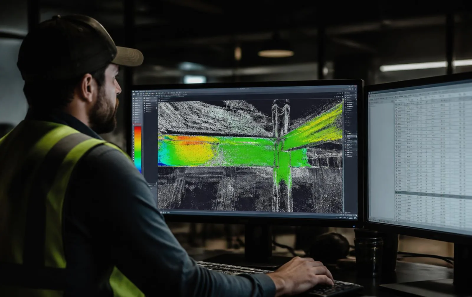
- Run a cloud-to-mesh or cloud-to-BIM deviation analysis in software capable of color-mapped comparison.
- Record deviation values numerically, not just as a heat map, so results can be compared against the tolerance band in a table.
- Flag any sample point exceeding the assigned tolerance for that element type.
- Route flagged elements back to modeling for correction or forward to the client as a documented exception if correction is not warranted.
This process is the practical version of what's described in more general terms in point cloud QA for scan-to-BIM and the underlying accuracy discussion in what does 5mm accuracy mean.
Element-by-element tolerance banding
Not every element in the model deserves the same tolerance band. Structural steel and slab-on-grade have different failure consequences and different achievable accuracy than a gypsum partition. A QC program should assign bands by element category and LOD, not apply one blanket ±10mm figure everywhere.
| Element category | Typical LOD | Tolerance approach |
|---|---|---|
| Structural framing (steel, precast) | LOD 300–400 | Linear deviation per member, tighter banding at connections |
| Slab / floor flatness | LOD 300 | Grid-sampled deviation from plane, not a single point check |
| Walls (plumb and location) | LOD 300 | Top/bottom deviation from vertical, plus base location |
| MEP routing | LOD 300–350 | Centerline deviation, clearance-critical zones checked separately |
| Architectural finishes | LOD 200–300 | Looser banding, coordination-level accuracy sufficient |
Banding decisions should be made before modeling starts, ideally documented in the 3D laser scanning scope of work, so the modeling team and the QC reviewer are working against the same criteria rather than negotiating tolerance after the model is delivered.
Discipline-specific checks
Generic deviation sampling misses failure modes that are specific to how a discipline actually uses the model.
Structural framing. Check member centerlines and connection points against the cloud, not just overall bounding geometry. A beam that passes an average deviation check can still have a connection point out of tolerance where it matters most.
Slab flatness. Use a grid-sampled deviation-from-plane method across the slab rather than a handful of spot checks. Isolated high points or low points are common in existing structures and a sparse sample will miss them.
Wall plumb. Measure deviation from vertical at both the top and bottom of the wall, not a single midpoint reading. A wall can read as plumb at mid-height and still be out of tolerance at the base connection.
MEP routing. Check centerline deviation along the run and treat clearance-critical zones (above ceilings, in shafts, at equipment rooms) as a separate tolerance category, since a deviation acceptable in open corridor space can be a clash in a tight mechanical room. This is the reason MEP scanning scopes typically call out clearance zones explicitly rather than relying on a single project-wide tolerance.
Model hygiene as a QC dependency
Deviation sampling can produce false results if the model's coordination framework is inconsistent, so model hygiene is a QC gate in its own right, not a separate housekeeping task.
- Shared coordinates. Confirm the Revit file's shared coordinate system matches the point cloud's registration coordinate system before running any deviation check; a coordinate offset will read as a tolerance failure across the entire model.
- Levels and grids. Verify levels match actual floor-to-floor elevations from the scan, not nominal design elevations, and that grids are locked to the same control network used for registration.
- Worksets. Check that worksets are organized by discipline or zone consistently, so QC reviewers can isolate categories for sampling without unlinking unrelated geometry.
- Naming. Confirm element and view naming follows the project standard; QC reports that reference "Level 2 East Wing Columns" only work if that naming is consistent between the model and the report.
A model that fails hygiene checks should be corrected before deviation sampling proceeds, because time spent sampling against a misaligned coordinate system has to be redone once the alignment is fixed.
Documenting tolerances in the BEP
Tolerance bands, sampling methods, and sign-off criteria belong in the BIM Execution Plan, not in an email thread or a verbal agreement between the modeler and the client. A BEP tolerance section should state:
- The capture tolerance the point cloud was registered to (±5mm) and the control method used to achieve it.
- The modeling tolerance assigned per element category, referencing the LOD assigned to each (LOD 200, LOD 300, LOD 400, or a mixed LOD 200–350 or LOD 200–400 range across categories).
- The deviation sampling method and minimum sample density per category.
- The exception process: how flagged deviations are documented, who reviews them, and what happens if a deviation cannot be corrected.
- The sign-off authority for each gate in the QC workflow.
Firms that skip this documentation tend to discover, mid-project, that the client assumed fabrication-level tolerance while the scope was scanned and modeled for design coordination. The BEP is the place that assumption gets tested before it becomes a change order.
Gate-by-gate QC workflow
- Control verification. Confirm survey control network accuracy and tie-in before scanning begins.
- Registration QC. Verify the registered point cloud meets ±5mm capture tolerance using independent check points.
- Modeling kickoff review. Confirm the BEP's tolerance bands and LOD assignments are available to the modeling team before work starts.
- In-progress spot checks. Sample a subset of modeled elements against the cloud at defined milestones, not only at final delivery.
- Full deviation sampling. Run category-by-category cloud-to-model deviation analysis across the completed model.
- Exception review. Route flagged elements to correction or document them as accepted exceptions with engineering sign-off.
- Model hygiene audit. Verify shared coordinates, levels, grids, worksets, and naming before final packaging.
- QC report issuance. Compile registration accuracy, sampling method, deviation results, and exceptions into a single report.
- Client sign-off. Obtain sign-off from the reviewing engineer or BIM manager referencing the tolerance thresholds in the BEP.
This sequence mirrors the broader coordination checks described in as-built accuracy and design coordination, applied specifically to the tolerance-analysis use case rather than general as-built accuracy.
FAQ
What is the difference between capture, modeling, and fabrication tolerance?
Capture tolerance is the accuracy of the registered point cloud itself, typically ±5mm. Modeling tolerance is the deviation allowed between the point cloud and the modeled Revit geometry, typically ±10mm at LOD 300. Fabrication tolerance is set by the trade contractor's shop standards and is usually tighter than modeling tolerance, which is why fabrication-ready models require additional verification passes.
How is scan-to-BIM tolerance analysis actually performed?
A QC technician samples cloud-to-model deviation at defined intervals across structural, envelope, and MEP elements, records the deviation against the tolerance band assigned to that element type, and flags any point exceeding the band for review or re-scan before the model is released.
What should a BIM QC report include?
A QC report should list control network accuracy, registration error, the sampling method and sample count, deviation results by element category, any flagged exceptions with resolution notes, and a sign-off statement referencing the tolerance thresholds set in the BEP.
Why does slab flatness need a different tolerance check than wall plumb?
Slab flatness is evaluated against a surface tolerance sampled across a grid, while wall plumb is evaluated as a linear deviation from vertical at top and bottom reference points. Treating both with a single generic tolerance produces false passes or false failures.
Who signs off on model tolerance before it moves to design coordination?
Typically the scan-to-BIM QC lead verifies registration and deviation sampling, then a licensed engineer or BIM manager on the receiving team confirms the tolerance band is acceptable for the intended use, whether that is design coordination, structural analysis, or fabrication.
Does model hygiene affect tolerance analysis results?
Yes. Inconsistent shared coordinates, mislabeled levels or grids, or duplicated worksets can shift geometry silently between files, producing apparent tolerance failures that are actually coordination errors rather than modeling errors.