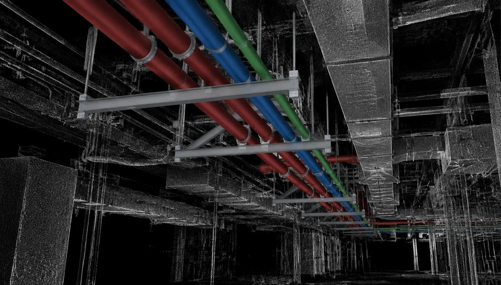
TL;DR
TL;DR: Prefab racks, risers and skids meet the real building for the first time at installation, so fabricate against measured existing conditions, not record drawings. Ask for a registered point cloud at ±5mm, LOD 300 model faces within ±10mm for general coordination, LOD 350 at tie-ins and LOD 400 (±6mm) only in fabrication zones. Plan above-ceiling capture, set clash tolerance with model tolerance in mind, and require a deliverable that states LOD per zone, tolerance, modeling convention and unverified geometry.
Prefabrication and MEP contractors need scan-to-BIM because a rack, riser or skid built in the shop meets the real building for the first time at installation, and record drawings rarely describe that building closely enough. Before releasing anything to fabrication, ask for a registered point cloud at ±5mm, an existing-conditions Revit model with model faces within ±10mm of the cloud at LOD 300 for general coordination, LOD 350 at the tie-ins where new work connects to old, and LOD 400 (model faces within ±6mm) only in the zones you will actually fabricate against. Above-ceiling capture has to be planned, not assumed, and the deliverable should state tolerance, LOD per zone and which elements were never seen by the scanner.
Why do prefab and MEP trades need verified existing conditions?
Prefabrication moves the moment you discover an error. On a stick-built job, an installer who finds a beam lower than drawn cuts a new offset in the field. On a prefab job, that beam is found when a finished multi-trade rack is lifted into a corridor and does not fit. The fix is refabrication, another lift and lost schedule, and the spool or rack that did not fit is scrap.
The assemblies most exposed are the ones that depend on existing geometry at both ends:
- Corridor and ceiling racks that must clear existing structure, sprinkler mains and ductwork that are staying.
- Risers that pass through a stack of existing slab openings and sleeves, where each floor's opening has to line up with the next.
- Mechanical room assemblies and skids that connect to existing headers, equipment nozzles and electrical gear.
- Tie-ins where a new branch meets an existing main at a specific elevation.
Record drawings show design intent, sometimes decades out of date. A laser scan shows what was built. The reasoning behind matching accuracy to each MEP decision is covered in detail in How As-Built Accuracy Shapes MEP Design Decisions.
What LOD should a prefab or MEP contractor ask for?
Level of Development describes what is modeled and how far each element is developed. The BIMForum LOD Specification, 2024 Part I gives the definitions that matter here:
- LOD 300: quantity, size, shape, location and orientation "can be measured."
- LOD 350: all of that plus "interfaces with adjacent or dependent Model Elements"; BIMForum says it is "sufficiently developed to support construction-level coordination" and "usually requires craft knowledge."
- LOD 400: "detail sufficient for fabrication, assembly, and installation," roughly shop-drawing level, and BIMForum notes that "most models contain few LOD 400 elements."
For existing conditions that translates into a split by zone, not one number for the whole building:
| Zone or element | LOD to ask for | Model-face tolerance | Why |
|---|---|---|---|
| General architecture and structure | LOD 300 | ±10mm | Reliable background for routing and clash detection |
| Existing MEP you route around | LOD 200 to 300 | ±10mm at LOD 300 | You need to know where it is, not how it connects |
| Existing mains, headers and equipment you tie into | LOD 350 | Stated in the proposal | Connection points and interfaces must be modeled |
| Structure and openings you fabricate against (rack supports, riser openings, equipment pads) | LOD 400 | ±6mm | Fabrication dimensions are pulled directly from these faces |
Asking for LOD 400 everywhere is a common and expensive mistake. It multiplies modeling labor across areas where a detailer will never pull a dimension. Our comparison of LOD 200 vs 300 vs 400 walks through how to split levels by area.
What tolerance should you ask for, and what does it cover?
Two accuracy figures matter, and they describe different things. The USIBD Level of Accuracy Specification Guide (C120, Version 2.0, 2016) calls them measured accuracy, achieved by the measurements themselves, and represented accuracy, achieved "once the measured data is processed into some other form such as line work or a model." The guide states that represented accuracy "can only be even or less accurate than the measured accuracy."
In our terms:
- Measured: the registered point cloud, at ±5mm.
- Represented: the Revit model, with faces within ±10mm of the registered cloud at LOD 300 and ±6mm at LOD 400.
For a detailer this means three practical things. First, a dimension pulled from an LOD 300 element carries the ±10mm model tolerance, not the ±5mm cloud figure, so check critical dimensions against the cloud itself before release. Second, the model tolerance stacks with your own shop and field tolerances; it does not replace them. Third, ask the provider to state the modeling convention (to faces or to centerlines) so your detailer knows what a dimension actually references. If a rack support or riser opening needs tighter geometry than LOD 300 gives, scope that area at LOD 400 rather than tightening the whole model.
How is above-ceiling space captured?
Most of the geometry a mechanical or electrical contractor fabricates against sits above a lay-in ceiling. It does not get captured by accident. The approach described in MEP and above-ceiling scanning explained is a planned sequence:
- Access planning. Tile-lift locations along mains and at key intersections are agreed with facilities before the field day, which matters most in occupied buildings.
- Hybrid capture. Mobile LiDAR covers general circulation; static setups through each opening capture the density above the ceiling.
- Classification. Duct, piping, conduit, cable tray and sprinkler systems are separated by discipline and modeled to the LOD each decision needs.
- Coordination handoff. Clash-ready geometry is delivered into your Revit or Navisworks coordination workflow.
For fabrication, ask for one more step: a coverage map that marks tile-lift locations and areas that were not visible, so nobody mistakes an inferred run for a measured one.
Know the limit. A scanner records surfaces it can see. It does not see rebar or post-tension cables inside a slab, pipe behind insulation, or anything behind a hard ceiling that was not opened. Core and sleeve locations still need the structural drawings, ground-penetrating radar or field verification, and the model should flag concealed or interpolated elements as not field-verified.
How do you coordinate a fabrication model against the scan?
Coordinate against both the existing-conditions model and the point cloud, on one shared coordinate system.
Link everything to the same frame. The point cloud, the existing-conditions model and your fabrication model should share coordinates from day one. A written coordinate note from the provider settles how the cloud was registered and which Revit positioning option to use.
Set clash tolerance with the model tolerance in mind. In Navisworks, tolerance "controls the severity of the clashes reported and the ability to filter out negligible clashes." A hard clash is reported when geometry intersects "by a distance of more than the set tolerance," and a clearance clash when it "comes within a distance of less than the set tolerance." A hard-clash tolerance tighter than the ±10mm model tolerance of LOD 300 elements is testing modeling noise, not the building. Use clearance tests for what fabrication actually needs: insulation thickness, hanger space, valve access and install clearance around the rack.
Check the cloud where it counts. Before a spool or rack goes to the shop, overlay the fabrication model on the point cloud at supports, penetrations and tie-in points. The cloud shows conditions the existing model simplified, such as sagging duct, out-of-plumb risers and hangers that were never modeled.
Run a release check. Review the registration report for the specific area, spot-check critical dimensions in the field, and confirm the LOD and tolerance of every element your detailer dimensioned from. Our tolerance and clash detection guide covers setting up those rules.
What should you request in the deliverable?
Write these into the scope so every quote prices the same thing:
- Registered point cloud in RCP/RCS for Revit and Navisworks and E57 for the archive, split by floor or zone on one coordinate frame.
- Registration report with residuals for the areas you will fabricate against, not only a project-wide figure.
- Coordinate note stating the coordinate system, control and recommended positioning in Revit.
- Native Revit model with an LOD table by zone and discipline, and the stated model-face tolerance for each level.
- Modeling convention for pipe, duct and structure (faces or centerlines).
- System classification by discipline and system, so trades can isolate their own work.
- Flags on unverified geometry: concealed, inferred or interpolated elements marked as such.
- Coverage map showing tile-lift locations and areas that were not captured.
For a fuller checklist, see how to write a 3D scan deliverable spec.
What does it cost and how long does it take?
Scanning and a registered point cloud run $0.05–$0.20 per sq ft; modeling is priced on top by LOD and discipline. From our published modeling rates:
| Modeling scope | Modeling cost per sq ft | What you get |
|---|---|---|
| LOD 300, all disciplines (arch/struct/MEP) | $0.45–$0.90 | Ductwork, piping, conduit and equipment at design-level accuracy |
| LOD 350, MEP-dense, all disciplines | $0.75–$1.75 | Interfaces between systems modeled; hangers, connections; clash-detection ready |
LOD 400 fabrication zones are quoted separately, by scope. The full breakdown, including minimums and sample budgets, is in Scan-to-BIM Pricing: What a Revit Model Really Costs.
On schedule, field capture covers 80,000 to 120,000 sq ft per field day, with above-ceiling capture adding field time. The registered point cloud follows in 3 to 5 business days, LOD 200 in 10 to 15 business days for about 100,000 sq ft, and LOD 300 in 3 to 5 weeks. Detailers can start routing against the point cloud while the model is built, and modeling can be phased by area so fabrication zones come first when the shop schedule depends on them.
How should a prefab or MEP contractor get started?
Send the drawings you have, mark the zones you plan to fabricate against, and tell us when shop drawings are due. We scope MEP and above-ceiling scanning and scan-to-BIM for Revit MEP renovations around those zones and return a quote within one business day. Contact us to start.
Sources
- BIMForum, Level of Development Specification, 2024 Part I: LOD 300, LOD 350 and LOD 400 definitions and BIMForum interpretations.
- U.S. Institute of Building Documentation, Document C120, Level of Accuracy (LOA) Specification Guide, Version 2.0 (2016): measured accuracy versus represented accuracy.
- Autodesk, Navisworks Manage 2017 Help, Glossary: definitions of tolerance, hard clash and clearance clash.