TL;DR
3D laser scanning for deformation monitoring has limitations, primarily where movement is smaller than the scanner's measurement noise (typically a few millimeters). Its effectiveness is reduced by inconsistent surface reflectivity and steep incidence angles, which can be mitigated with survey targets. The entire analysis depends on a completely stable survey control network; any movement in control points will invalidate the results. Environmental factors like thermal expansion and live loads must be controlled or accounted for to avoid misinterpreting normal structural responses as long-term deformation. While excellent for detecting broad surface patterns like bowing or settlement, laser scanning is not a replacement for high-precision, discrete-point tools like strain gauges or total stations when sub-millimeter accuracy is required.
Why 3D Laser Scanning Has Limits for Deformation Monitoring
TL;DR
- Scanning cannot reliably detect movement smaller than its measurement noise, typically a few millimeters.
- Surface properties like reflectivity and color introduce variability that can be mistaken for deformation.
- The entire analysis depends on a survey control network that is verifiably stable between measurements.
- Environmental factors like temperature and structural loading cause real-time changes that can mask long-term trends.
- Laser scanning captures broad deformation patterns well but is not a substitute for high-precision point measurement tools.
Jump to: What is the primary accuracy limitation? · How does surface material affect monitoring results? · Why is a stable control network essential? · Can environmental factors skew the data? · What happens when the area of interest is blocked? · What is the difference between pattern detection and point precision? · Where to go next
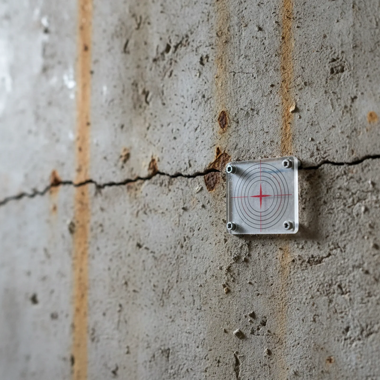
This guide is for engineers, asset managers, and project owners who specify structural monitoring services. It explains the practical and technical deformation monitoring limits of 3D laser scanning, helping you decide when it is the right tool and when it must be supplemented or replaced by other survey methodologies.
3D laser scanning provides a rich, comprehensive dataset of a structure's geometry at a specific moment. When repeated over time, these datasets can be compared to detect and quantify change. However, understanding the technology's inherent limitations is critical to designing an effective monitoring program and avoiding the misinterpretation of data. This is not a list of reasons to avoid scanning, but a guide to using it correctly.
What is the primary accuracy limitation?
The most significant limitation is the technology's precision relative to the magnitude of movement being studied. Every measurement system has an inherent level of random error, often called a "noise floor." For a typical terrestrial laser scanning project, the final registered point cloud accuracy is in the range of ±5mm. This means any single point in the cloud has an uncertainty of several millimeters.
If a monitoring program needs to detect structural movement of 1-2 millimeters, laser scanning is not the appropriate primary tool. The real-world movement would be lost within the statistical noise of the measurement system. Attempting to extract sub-millimeter data from a system with a multi-millimeter noise floor will produce meaningless results. It becomes impossible to distinguish a minuscule structural shift from a random data fluctuation. An explanation of what ±5mm accuracy means in practice shows how this tolerance zone affects all measurements derived from the data.
Alternative/Supplement: For monitoring that requires sub-millimeter precision, the correct instrument is often a robotic total station (RTS) locked onto high-precision survey prisms installed at discrete points. For purely vertical settlement monitoring, high-precision digital leveling provides even greater accuracy. These methods sacrifice area coverage for superior point-specific accuracy.
How does surface material affect monitoring results?
A laser scanner works by emitting a beam of light and measuring its return. The quality of that return signal is highly dependent on the surface it strikes. This introduces a significant variable in deformation studies.
- Reflectivity and Color: Dark, matte surfaces absorb more laser energy, resulting in a weaker, noisier return signal. Conversely, highly reflective or specular surfaces, like polished metal or glass, can scatter the laser beam in unpredictable directions, creating erroneous points or data voids.
- Angle of Incidence: When the laser beam strikes a surface at a steep, oblique angle, the resulting point measurement is less precise. The laser spot elongates on the surface, and small variations in the scanner's position can lead to larger apparent shifts in the measured point's location.
If the surface properties change between scans—for example, if a concrete wall gets wet, a steel beam is painted, or dust accumulates—the laser return will change. This change in signal can be misinterpreted by analysis software as a physical change in the structure's position.
Alternative/Supplement: The standard solution is to install permanent, high-contrast survey targets on the monitored surfaces. These adhesive targets have a consistent, known reflectivity and provide a clear, repeatable point for the scanner to measure in each epoch. This practice removes the variable of surface material from the equation, focusing the analysis on the movement of the targets themselves rather than the noisy native surface. The choice between mobile vs. terrestrial laser scanning can also influence how well the system handles varied surfaces, with tripod-based systems generally offering more control over challenging materials.
Why is a stable control network essential?
Deformation analysis works by aligning multiple point clouds, captured at different times, into a single, shared coordinate system. This alignment is governed by a network of fixed survey control points that are assumed to be perfectly stable. The entire analysis hinges on this assumption: if the control points move, the software will register this as movement in the structure.
An unstable control network is one of the most common sources of error in deformation monitoring, leading to false positives (detecting movement that didn't happen) or false negatives (missing movement that did). Control points can shift for many reasons:
- Ground movement from settlement, frost heave, or nearby excavation.
- Disturbance from construction activity.
- Instability of the object the control target is mounted on (e.g., a temporary wall, a vibrating piece of equipment).
A robust point cloud control plan for deformation analysis is non-negotiable. Without it, the comparison between epochs is invalid. The process is no longer comparing the structure to a fixed baseline but to a moving one, making the results unreliable for engineering decisions.
Alternative/Supplement: The control network must be established and verified by a licensed land surveyor. Control points should be anchored to structures or geology known to be stable, such as deep-driven rods, monuments anchored to bedrock, or portions of the building far removed from the area of concern. For critical projects, the stability of the control network itself should be periodically re-verified against a higher-order geodetic network.
Can environmental factors skew the data?
Structures are not static; they respond dynamically to their environment. These short-term movements are real but can be easily confused with the long-term, permanent deformation that a monitoring program is typically designed to track.
- Thermal Expansion and Contraction: Materials expand when heated and contract when cooled. A long steel beam or concrete slab can change in length by several millimeters or more over a daily temperature cycle. A scan taken on a cool morning will show a different geometry than a scan taken on a hot afternoon. This thermal effect can be larger than the ±5mm accuracy of the scan data.
- Live Loading: The weight of people, equipment, stored materials, snow, or wind pressure causes structures to deflect. A warehouse floor will measure differently when it is empty versus when it is fully stocked. A bridge will deflect as traffic passes over it.
If one scan is captured on a cool day with no load and the next is on a hot day with a full live load, the resulting deviation analysis will show significant change. However, this change is not permanent deformation but a temporary elastic response. Attributing it to settlement or structural failure would be a critical error.
Alternative/Supplement: The monitoring plan must control for these variables. This involves scheduling scans for the same time of day and under similar loading conditions for each epoch. More advanced programs will involve installing temperature, strain, or load sensors to record environmental conditions concurrently with the scan. This allows the team to correlate the measured geometric changes with environmental data, separating the temporary response from the permanent deformation trend.
What happens when the area of interest is blocked?
Laser scanning requires a direct line of sight from the scanner to the surface being measured. Anything that blocks this line of sight creates a "shadow" or data void in the point cloud. In a deformation monitoring context, this is known as occlusion.
On an active construction site or in a functioning industrial facility, the environment is constantly changing. A pallet of materials, a piece of equipment, or new construction can easily block the view of a critical monitoring point that was visible in the previous scan. When this happens, there is no data for that specific location in the new scan, creating a gap in the time-series analysis. It becomes impossible to determine if that part of the structure has moved because there is no data to compare. While a provider can take steps to prepare a site for a 3D laser scan, complete control over a dynamic environment is not always possible.
Alternative/Supplement: A well-designed monitoring program anticipates potential occlusions. This may involve placing multiple, redundant survey targets around a critical area, ensuring that at least one is likely to be visible in future scans. In some cases, photogrammetry can supplement the scan data, as a camera may be able to capture an occluded area from a different vantage point. For very specific points, traditional survey methods or embedded sensors that do not rely on line-of-sight may be required.
What is the difference between pattern detection and point precision?
It is crucial to distinguish between detecting a *pattern* of deformation and measuring a *precise change* at a single point. 3D laser scanning excels at the former but has clear limits for the latter.
Because a scanner captures millions of points over a large area, it is an unparalleled tool for visualizing the overall behavior of a structure. A deviation heat map can instantly reveal that a floor is sagging in the middle, a retaining wall is bowing outward, or an entire building is tilting. It provides context and shows the full extent of a geometric change. This is the primary strength of using 3D laser scanning for deformation studies.
However, it is not the right tool for answering the question, "Exactly how much has this specific crack widened, to the nearest tenth of a millimeter?" The point density and accuracy are insufficient for that level of discrete precision. The scanner captures the "what" and "where" of deformation on a macro scale, but other tools are needed for the "how much" on a micro scale.
Alternative/Supplement: For high-precision measurement at discrete points, the appropriate tools are geotechnical or structural sensors. These include:
- Crack gauges / Demec points: To measure change in the width of a specific crack.
- Strain gauges: To measure material stress at a critical point.
- Tiltmeters and inclinometers: To measure rotation or inclination with high precision.
- Extensometers: To measure the change in distance between two points.
The most effective monitoring programs often use a hybrid approach: 3D laser scanning provides broad area coverage to identify concerning trends, and specialized sensors provide high-precision data at the most critical locations identified by the scans.
Selecting the Right Tool for the Job
The appropriate monitoring method is dictated by the expected magnitude of movement. Using a tool that is too precise is inefficient, while using one that is not precise enough yields useless data.
| Expected Movement | Primary Method | Secondary/Supplementary Method | Common Use Case |
|---|---|---|---|
| > 10 mm | 3D Laser Scanning (Mobile/Terrestrial) | GPS, Aerial Survey (Drone) | Large-scale site settlement, landslide monitoring, excavation progress |
| 5–10 mm | Terrestrial Laser Scanning (TLS) | Robotic Total Station (RTS), Digital Leveling | Building settlement, beam/slab deflection, retaining wall movement |
| 1–5 mm | Robotic Total Station (RTS) | TLS (with targets), Precision Digital Leveling | Precise structural settlement, bridge deflection, facade monitoring |
| < 1 mm | Geotechnical/Structural Sensors | High-Precision RTS, Interferometric Radar (InSAR) | Crack propagation, strain measurement, critical component monitoring |
Where to go next
Understanding these limitations allows for the creation of a robust and reliable monitoring program. By combining 3D laser scanning's strength in area-wide pattern detection with the precision of other survey methods, engineers and asset owners can get a complete picture of structural behavior. For a deeper dive into common issues, see the guide on why 3D laser scanning struggles with some deformation tasks or explore the requirements for a successful building scanning structural assessment.