TL;DR
Point cloud registration aligns individual scan setups or mobile trajectories into one coordinate system, and its accuracy — not the Level of Development chosen later — sets the ceiling on what a Scan to BIM model can represent. Target-based registration, cloud-to-cloud (ICP) alignment, and SLAM-based mobile capture each need different controls, and a defensible registration report states cloud-to-cloud RMS, maximum single-station residual, control-network closure, and station/control-point counts. Drift accumulates over long corridors, stair cores, and multi-floor buildings unless control ties constrain it, and disorganized scan groups, naming, and coordinate systems cost modeling teams hours before a single wall gets drawn. Zealot registers point clouds to ±5mm and builds LOD 200-350 models on top of that registration.
Point Cloud Registration in Scan to BIM
TL;DR
- Point cloud registration aligns individual scans or mobile trajectory segments into one coordinate system, and it sets the accuracy ceiling for everything modeled afterward.
- Target-based registration, cloud-to-cloud (ICP) alignment, and SLAM-based mobile capture each require different controls and produce different accuracy characteristics.
- A defensible registration report states cloud-to-cloud RMS, maximum single-station residual, control-network closure, and the number of stations and control points used.
- LOD describes modeled detail, not positional accuracy — a highly detailed model can still sit on a poorly registered cloud.
- File structure — scan groups, naming conventions, RCP/RCS organization, shared coordinates — determines how many modeling hours a project burns before geometry gets drawn.
Jump to: What Registration Means | Registration Methods | Bundle Adjustment | Registration Reports | Error Propagation | Drift | File Structure | Verification
What does point cloud registration actually mean?
Every laser scan is captured from a fixed tripod position, or as a continuous stream from a moving mobile unit, and each capture initially exists in its own local coordinate space. Registration is the mathematical process of finding the rotation and translation that moves each of those local point clouds into a single shared coordinate system, so that a wall scanned from station 12 lines up exactly with the same wall scanned from station 13.
This step happens before any BIM modeling begins, and it is arguably the single most consequential step in the entire reality capture pipeline. A registered point cloud is the raw material the modeling team works from — every wall, duct, and column drawn later inherits whatever positional accuracy the registration achieved. Software can render a beautifully colorized, dense point cloud that still contains inches of internal misalignment if registration was rushed or under-controlled, and that misalignment is not always visible on screen. It shows up later as doubled surfaces in a section cut, or as a column that doesn't line up between floors. Understanding registration is what separates evaluating a point cloud vs a BIM model as reliable source data versus decorative visualization.
What are the main registration methods, and how is each controlled?
Three approaches dominate current practice, and most real projects blend more than one.
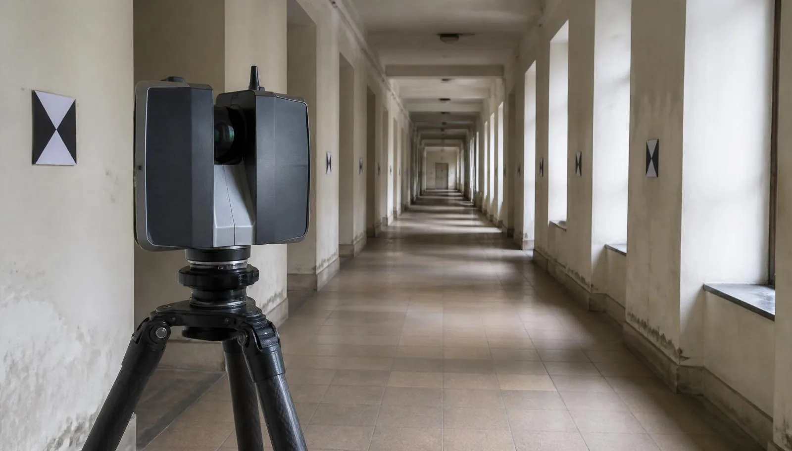
Target-based registration places surveyed reference targets — spheres, checkerboards, or flat black-and-white markers — in overlapping zones between scan setups. The scanner captures each target's precise center point from multiple stations, and registration software solves for the transformation that makes those shared target positions coincide. This method is controlled by target density, geometric distribution (targets spread in three dimensions, not clustered on one wall), and how many stations see each target. It remains the gold standard for high-accuracy interior scan to BIM work because it doesn't depend on the room having distinctive geometry.
Cloud-to-cloud registration, typically run through an Iterative Closest Point (ICP) algorithm, skips targets and instead matches overlapping surface geometry between adjacent scans. It's faster in the field and works well in spaces with plenty of geometric variation — furniture, irregular walls, structural elements — but struggles in long, repetitive corridors or open rooms with few distinguishing features, where the algorithm can converge on a locally consistent but globally wrong alignment. Control here comes from overlap percentage between scans (typically 30-50% minimum) and manual verification of alignment residuals at each pair.
SLAM-based mobile capture, used in handheld and cart-mounted mobile lidar systems, builds its own trajectory in real time by continuously matching consecutive frames while the operator walks. It's dramatically faster over large areas but accumulates drift over distance because each frame's position depends partly on the accuracy of the frame before it. Control comes from loop closures — walking back through previously scanned areas so the algorithm can detect and correct accumulated drift — and from tying the trajectory to surveyed control points at intervals, discussed further in the guide comparing mobile vs terrestrial laser scanning.
What does bundle adjustment do in the registration process?
Bundle adjustment is the optimization step that runs after initial pairwise alignments (target-based or cloud-to-cloud) have been computed. Rather than accepting each scan-to-scan alignment independently, bundle adjustment simultaneously solves for the positions of all scans and all shared reference points as one global least-squares problem, distributing residual error evenly across the network instead of letting it accumulate in one direction. This is conceptually similar to how a traditional survey network adjustment redistributes closure error across a loop of control points. A well-run bundle adjustment produces a project-wide RMS error figure that is meaningfully lower than the error of any single scan pair, which is why registration reports quote network-level statistics rather than individual pair alignments.
What should a registration report actually state?
A registration report is a data table, not a marketing summary, and it should let a reviewer independently judge whether the dataset meets the contracted accuracy tier. At minimum it should include:
| Report element | What it tells the reviewer |
|---|---|
| Cloud-to-cloud RMS error | Average alignment error across all scan pairs in the network |
| Maximum single-station residual | Worst-case error at any individual scan setup, flags weak links |
| Control-network closure | How well surveyed control points close the loop across the whole site |
| Number of stations | Scan density relative to project size and complexity |
| Number of control points | Independent ground-truth anchors constraining the whole registration |
| Target/control distribution | Whether references are spread through the volume or clustered |
Reports that omit maximum residual and only quote an average RMS can hide a single badly registered station that will produce a visibly wrong wall in one part of the model while the rest of the building looks fine. Reviewers should ask for both numbers, and for how many control points tie the registration to independently surveyed geometry, which is covered in more depth in the discussion of vetting point cloud accuracy before hiring a provider.
How does registration error propagate into the modeled geometry?
Modeling teams draw walls, ducts, and structural elements by snapping to point cloud surfaces, so any registration error present in the cloud transfers directly into the modeled geometry — modeling software has no way to distinguish a true surface from a misaligned one. If two adjacent scans are registered 8mm apart at their shared wall, the modeler either draws the wall at one scan's position (accepting a local error) or splits the difference, and either way the resulting Revit element carries that registration error forward into every clash detection run, dimension check, and fabrication drawing that references it.
This is precisely why registered accuracy and LOD have to be evaluated separately, a distinction detailed further in why point cloud accuracy matters for BIM coordination. LOD 300 or 350 geometry built on a cloud registered to ±5mm carries that accuracy forward into coordination workflows; the same LOD built on a cloud with unreported or unchecked registration error carries an unknown, potentially much larger error, regardless of how detailed the model elements look.
Why does drift show up in long corridors, stair cores, and multi-floor buildings?
Drift is the gradual accumulation of small registration errors as a dataset extends across distance, and it appears most visibly in three conditions. Long, repetitive corridors offer cloud-to-cloud algorithms little distinctive geometry to lock onto, so small errors compound scan-to-scan down the hallway's length. Stair cores and elevator shafts are the vertical links that tie floor-to-floor registrations together, and if those connecting scans are sparse or poorly overlapped, floors above and below can rotate or shift relative to each other even when each floor looks internally consistent. Multi-floor buildings amplify both problems simultaneously, since horizontal drift on each level compounds with vertical misalignment between levels.
| Drift risk area | Typical cause | Mitigation |
|---|---|---|
| Long corridors | Repetitive geometry, low ICP confidence | Targets at regular intervals, control points every 50-100 ft |
| Stair cores / shafts | Sparse vertical scan overlap | Dedicated vertical control ties, redundant scans per level |
| Multi-floor buildings | Compounding horizontal + vertical error | Site-wide control network surveyed independently of scan data |
| Open/symmetric rooms | Few distinguishing features for cloud-to-cloud | Target-based registration instead of pure ICP |
Surveyed control networks are what stop drift from compounding unchecked — an independently surveyed set of points, tied into the registration at intervals, gives the bundle adjustment external ground truth to constrain against rather than letting the whole dataset float relative to only itself. Projects requiring tight dimensional confidence, such as those needing scan to BIM tolerance analysis, should confirm control density explicitly rather than assuming it.
Why does file structure matter as much as registration accuracy?
A perfectly registered point cloud delivered with disorganized files still costs a modeling team hours it shouldn't. File structure covers how scan data is grouped and named, and how coordinate systems are shared across the deliverable, and each piece has a direct cost impact if handled poorly:
- Scan groups by level/zone — clouds should be segmented so a modeler can isolate a single floor or wing without loading the entire building's point data, which matters enormously for large projects and is discussed further in the guide to organizing point cloud data for scan to BIM.
- Consistent naming — station and group names should map predictably to physical locations (e.g., "L2-EastWing-Corridor") rather than default scanner-generated IDs, so a modeler can find the right data without opening every file.
- RCP/RCS structure — Autodesk ReCap project files (.rcp) should reference individual scan files (.rcs) in a clean hierarchy that mirrors the building's levels, with no orphaned or duplicate references that bloat file size and confuse coordination.
- Shared coordinates — the registered cloud's coordinate system should match the architect's Revit shared coordinates or an agreed site datum, so linking the cloud into a model doesn't require a manual, error-prone repositioning step.
Sloppy structure doesn't just annoy modelers — it directly inflates modeling hours, since every minute spent hunting for the right scan group or manually repositioning a misaligned coordinate system is billed time that adds no value to the deliverable. This is one of the recurring findings in reviews of why poor point clouds disrupt BIM coordination.
How can an architect verify a registered cloud before modeling starts?
Verification doesn't require survey expertise, just a short checklist applied before authorizing modeling work:
- Request the registration report and confirm it states cloud-to-cloud RMS, maximum single-station residual, control-network closure, and station/control-point counts — not just a single headline accuracy figure.
- Compare the reported accuracy against the contracted tier; a project specifying ±5mm accuracy should have a report showing figures consistent with that tolerance, not silence on the topic.
- Spot-check a handful of field-verifiable dimensions (door widths, ceiling heights, column spacing) against the cloud in a viewer.
- Open the file structure and confirm scans are grouped logically by level or zone, named consistently, and set to the project's shared coordinate system.
- Ask specifically how stair cores or elevator shafts were tied together if the project spans multiple floors, since that is the most common place unreported drift hides.
This checklist mirrors the broader due-diligence steps outlined in Revit checks before hiring scan to BIM services, and applying it before modeling begins is far cheaper than discovering a registration problem after a coordination model is half built. Zealot registers every point cloud to ±5mm accuracy before modeling begins, delivering LOD 200-350 Revit models with a registration report on request; questions about a specific dataset can be directed to 614-210-3679.