TL;DR
Engineering-grade existing conditions documentation requires discipline-specific specifications. Structural engineers need data on member sizes, connections, and deflection baselines, often delivered as an LOD 300-350 structural model. MEP engineers require detailed plenum and mechanical room data for routing and clash detection, typically a LOD 300 MEP model showing major systems. Civil engineers use scan data for site grading, utility tie-ins, and topographic context, delivered as a site model or contours. The foundation for these deliverables is a registered point cloud with an accuracy of ±5mm, captured using a combination of mobile and terrestrial LiDAR. A precise scope of work outlining the deliverable, format, and required accuracy is essential to ensure the data is fit for engineering analysis.
Existing Conditions Documentation for Engineers
TL;DR
- Engineering documentation requires discipline-specific data for analysis, not just general geometry.
- Structural teams need member sizes, connection access, and deflection data, typically in an LOD 300-350 Revit model.
- MEP teams need detailed above-ceiling routing, clearances, and equipment locations from congested spaces.
- Civil/site teams need accurate grades, utility tie-ins, and topographic context relative to the structure.
- A clear scope of work that specifies the deliverable format, accuracy, and engineering use case is critical for success.
Jump to:
What is the goal of existing conditions documentation for engineers? · What documentation do structural engineers need? · What documentation do MEP engineers need? · What documentation do civil/site engineers need? · How do you specify deliverables for each discipline? · How does accuracy impact engineering analysis? · Where to go next
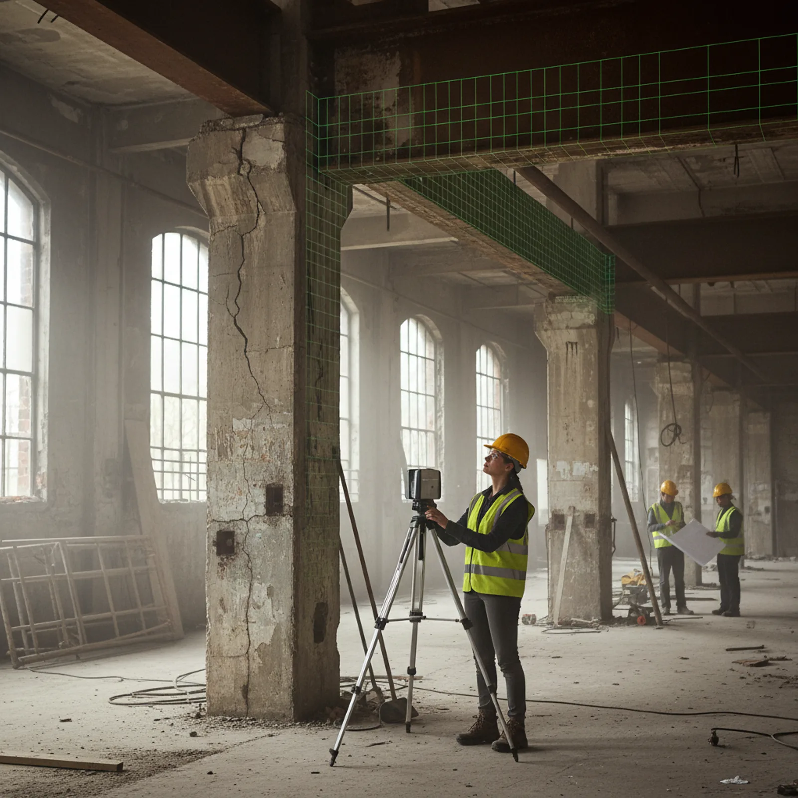
This guide is for structural, MEP, and civil engineers who are specifying or consuming existing conditions documentation for renovation, retrofit, and adaptive reuse projects. It provides a discipline-specific framework for defining the scope of work for 3D laser scanning services to ensure the deliverables are fit for engineering analysis.
Effective engineering relies on precise data. While general as-built drawings provide a starting point, they often lack the detail and verifiable accuracy needed for load calculations, system integrations, and clash detection. The decision to use reality capture is a decision to base engineering judgments on a high-fidelity digital record of the as-is state. This article breaks down what that record must contain for each major engineering discipline.
What is the goal of existing conditions documentation for engineers?
The primary goal is to create a reliable dataset that directly informs engineering analysis and design decisions. Unlike architectural as-builts, which focus on spatial layout and aesthetics, engineering documentation must capture specific, measurable properties of structural, mechanical, and site systems. This means moving beyond simple geometry to document element sizes, positions, clearances, and conditions with a known degree of accuracy.
The process begins with 3D laser scanning to create a registered point cloud of the facility. This dataset serves as the single source of truth. From the point cloud, discipline-specific deliverables are created. These can be intelligent BIM models (LOD 200–350), 2D drawings with precise annotations, or analysis reports derived directly from the point cloud data itself.
A well-defined scope of work is essential. The scope must clearly state what elements are to be captured, the required Level of Development (LOD) or accuracy, and the final deliverable format. Without this specificity, a provider might deliver a generic architectural model that is unsuitable for calculating structural loads or coordinating complex MEP routes.
What documentation do structural engineers need?
For structural analysis of an existing building, engineers require precise geometric data that confirms member sizes, locations, and conditions. Hand measurements are time-consuming and prone to error, especially at height or in complex assemblies. A point cloud provides a comprehensive and verifiable record.
The scope for structural documentation should request the capture of:
- Primary and Secondary Members: All beams, columns, joists, and trusses, including their profiles and dimensions.
- Connections: Visible connection details at beam-to-column and beam-to-girder intersections to assess accessibility for reinforcement or replacement.
- Slab and Floor Conditions: Data for floor flatness/levelness (FF/FL) analysis and to establish a baseline for deflection.
- Column Plumbness and Wall Verticality: Analysis to identify lean or deformation in primary vertical elements.
- Base Plates and Anchor Bolts: Locations and orientations of column bases, though specific bolt-level detail may require targeted high-resolution scans.
The deliverables are tailored to the analysis software. A common request is a structural Revit model at LOD 300 or 350, which can be imported into programs like RISA-3D, RAM, or ETABS. For deformation studies, the point cloud itself is the deliverable, used with specialized software to compare against a design model or a previous scan. This is particularly useful for establishing an accurate baseline for ongoing monitoring. A deeper dive on this topic is available in the guide to building scanning for structural assessment.
What documentation do MEP engineers need?
MEP engineers are primarily concerned with routing new systems and confirming the location and condition of existing ones. Congested plenums, packed mechanical rooms, and undocumented modifications are major sources of design rework and field conflicts. Laser scanning captures the dense reality of these spaces with a high degree of accuracy.
An MEP-focused scope should prioritize the capture of:
- Above-Ceiling Systems: All visible ductwork, piping, conduit, and cable trays, especially at major intersections and service rooms. The SOW should specify a minimum size to model (e.g., all pipes and conduits >2" in diameter).
- Mechanical Rooms: All major equipment (boilers, chillers, AHUs, pumps), including associated piping, valves, and access clearances. Capturing equipment data tags, if accessible, is also valuable.
- Service Entrances and Risers: The locations where primary electrical, water, and gas services enter the building and travel vertically through shafts.
- Clearances: Documenting the true clearance heights below structures and major systems is critical for routing large new ductwork or equipment.
Mobile LiDAR scanners like the NavVis VLX3 are highly effective for this work, capturing large floor plates and the systems above them at walking pace. For extremely dense mechanical rooms, tripod-mounted terrestrial scanners provide the higher resolution needed to resolve individual components. The most common deliverable is an MEP Revit model (LOD 300) that can be used for clash detection and design coordination, directly impacting as-built accuracy for MEP design decisions.
What documentation do civil/site engineers need?
For civil engineers, existing conditions documentation focuses on the interface between the building and the surrounding site. The primary goal is to establish accurate topography, locate visible utilities, and define project datums for site work and building tie-ins.
The scope for a civil/site scan should include:
- Site Topography: Surface grades immediately surrounding the building, including sidewalks, parking lots, and landscape features. This is used to plan drainage, grading, and accessibility.
- Visible Utility Features: The precise X, Y, and Z coordinates of manholes, valve boxes, utility poles, catch basins, and fire hydrants. This data provides surface-level evidence for subsurface utility engineering (SUE).
- Building Tie-In Points: The finished floor elevation (FFE), invert elevations of exiting pipes, and locations of exterior utility connections.
- Adjacent Structures: The location and massing of adjacent buildings, retaining walls, and other structures that could impact site logistics or design.
Scan data can be delivered as a 3D surface model in Civil 3D, 2D plan drawings with spot elevations and contour lines, or raw point cloud data. For large sites, data from terrestrial scanning can be combined with aerial data from drone photogrammetry. The point cloud data is also fundamental to performing accurate LIDAR volume calculations for cut-and-fill analysis during site preparation.
How do you specify deliverables for each discipline?
A successful project hinges on a clear specification. The scope of work must translate the engineering requirement into a concrete deliverable specification for the scanning provider. Using a table to define needs by discipline is an effective method. It ensures all parties understand the target elements, the required precision, the deliverable format, and the intended application. A well-written specification is the foundation for a useful deliverable. For more guidance, see this article on how to write a 3D scan deliverable spec.
| Discipline | Key Deliverable | Common Format(s) | Typical Specification | Engineering Use Case |
|---|---|---|---|---|
| Structural | 3D Structural Model | Revit (RVT), IFC | LOD 300-350. Model all primary and secondary structural members (beams, columns, joists). | Import into analysis software (RISA, RAM, ETABS); check for member conflicts; verify floor heights. |
| Deflection/Plumbness Analysis | PDF Report, Point Cloud (E57) | Point cloud-to-design model deviation analysis with color map. ±5mm registered cloud accuracy. | Assess floor sag, beam camber, and column lean; establish a baseline for monitoring. | |
| MEP | 3D MEP Model | Revit (RVT), Navisworks (NWD) | LOD 300. Model all visible pipes, ducts, and conduit >2" diameter. Model major equipment. | Clash detection against new design; planning new system routes; confirming clearances. |
| Annotated Panoramas | Web Viewer (e.g., NavVis IVION) | High-resolution imagery linked to point cloud locations, with measurements and tags. | Virtual site visits; confirm valve/damper locations; read equipment data tags. | |
| Civil/Site | 2D Topographic Plan | AutoCAD (DWG) | 1-foot contours; spot elevations at key features (corners, FFE, inverts). | Site grading design; drainage analysis; layout of new construction. |
| 3D Surface Model | Civil 3D (DWG), LandXML | Triangulated irregular network (TIN) surface generated from ground points. | Volumetric calculations; creating site profiles and cross-sections. |
How does accuracy impact engineering analysis?
The term "accuracy" in laser scanning refers to how closely a measurement conforms to its true value. For engineers, this is not an abstract concept; it directly impacts the reliability of analysis. ZEALOT's registered point cloud deliverable has a network accuracy of ±5mm. This means any two points within the registered cloud are correctly located relative to each other within that tolerance.
This level of accuracy is more than sufficient for most design coordination and clash detection tasks. For example, confirming a 12-inch clearance for a new duct run is easily achieved. However, certain engineering tasks demand a closer look. A scan-to-BIM tolerance analysis might be required for fitting prefabricated components into an existing structure.
For highly sensitive structural analysis, such as verifying the camber of a steel beam or checking the placement of anchor bolts to sub-millimeter precision, the scanning strategy must be adjusted. This often involves using a high-precision terrestrial scanner at close range and may include physical targets to enhance the local accuracy in critical areas. It is vital to communicate these specific, high-precision requirements in the scope of work so the scanning provider can deploy the appropriate hardware and methodology.
Where to go next
Specifying existing conditions documentation by discipline ensures that the data delivered is directly applicable to engineering analysis. By clearly defining the required elements, accuracy, and format, engineers can get a reliable dataset that reduces risk and informs better design. This process is fundamental to modern renovation and retrofit workflows.
To learn more about the foundational data, read about how 3D laser scanning supports existing conditions. To properly vet a provider for this type of work, consult this checklist for how to evaluate 3D laser scanning services in the United States.