TL;DR
Choosing the right Scan to BIM partner for a structural retrofit requires evaluating more than just point cloud accuracy. Engineers must verify a provider's specific experience with structural projects, including their methods for capturing encased members and documenting connection details. It is critical to confirm they use true Revit structural families and can produce a clean analytical model suitable for export to analysis software. Scrutinize their process for cross-referencing scan data with historical drawings to identify discrepancies in member sizes or locations. The final deliverable must support structural engineering workflows, not just architectural visualization. A rigorous vetting process based on project-specific evidence is necessary to prevent costly rework.
Comparing Scan to BIM Partners for Structural Retrofits
TL;DR
- Evaluate partners on their specific experience with structural projects, not just general BIM modeling.
- Confirm their methodology for modeling with true structural Revit families and creating clean analytical lines.
- Verify their process for comparing scan data against archive drawings to identify deviations.
- Assess their capability to document complex conditions like connections, camber, and member deformation.
- Request project-specific evidence, including sample models and clash reports, to validate their claims.
Jump to:
What defines a provider's experience with structural retrofits? · How do providers capture hard-to-reach or encased structural elements? · What is the process for verifying member sizes against old drawings? · Why is it important that a partner models with real structural families? · Can a Scan to BIM model be used directly in structural analysis software? · How should complex connection conditions be documented? · How do Scan to BIM services support seismic or strengthening projects? · How to Evaluate and Score Potential Partners · Where to go next
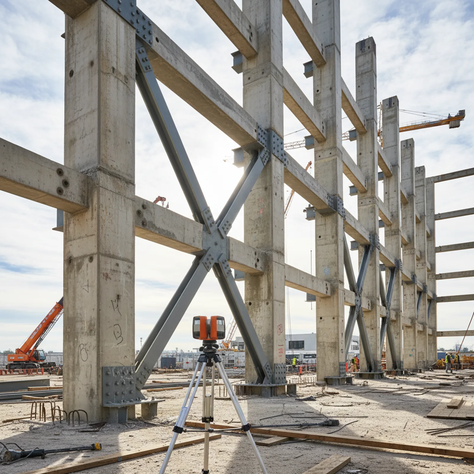
This guide is for structural engineers and engineering firms tasked with selecting a partner for Scan to BIM services on a retrofit project. Not all providers are equipped to meet the specific demands of structural engineering. The decision requires looking past marketing claims and focusing on the technical capabilities that directly impact analysis, design, and documentation workflows.
The goal is to provide a framework for comparing potential partners based on criteria unique to structural work. This includes their approach to modeling framing, verifying member sizes, handling analysis-ready deliverables, and capturing conditions relevant to seismic upgrades or member strengthening. By asking the right questions and demanding specific proof, engineering teams can select a provider that delivers a truly valuable asset, not a simplified architectural model that requires a complete rebuild.
What defines a provider's experience with structural retrofits?
A provider's general experience in Scan to BIM does not guarantee competence in structural applications. A portfolio filled with architectural models or MEP system documentation is not sufficient evidence. Structural retrofits demand a distinct skill set focused on load-bearing elements, their connections, and their precise geometric state.
When vetting a partner, request to see examples of as-built structural models they have previously delivered. Evaluate whether these models contain properly classified elements: columns are columns, beams are beams, and braces are braces, each with correct orientation and justification. A partner experienced in building scanning for structural assessment will be able to provide these work samples and speak fluently about the challenges of modeling different structural systems, from historic heavy timber to modern steel frames. Their team should understand the difference between a model for visualization and one intended for engineering analysis.
How do providers capture hard-to-reach or encased structural elements?
Structural elements are often obscured by finishes, located at dangerous heights, or encased in concrete or fireproofing. A prospective partner's data capture strategy must account for these challenges. The choice of hardware is a primary indicator of their capability. A combination of tripod-mounted terrestrial scanners for high-precision, static setups and mobile LiDAR systems like the NavVis VLX3 for rapid capture of large floor plates is a common and effective approach. For an 80,000–120,000 sq ft facility, this dual-hardware method balances speed with the detail needed for structural verification.
Inquire about their methodology for scanning areas with limited line of sight. For elements encased in spray-on fireproofing, a competent provider will model to the outer surface and note the condition, as LiDAR cannot penetrate it. For concrete-encased steel, they must specify that ground-penetrating radar (GPR) or selective demolition (performed by others) is required for verification. An experienced firm will proactively identify these limitations in their scope of work, demonstrating foresight and a practical understanding of the technology's limits.
What is the process for verifying member sizes against old drawings?
Existing record drawings are a valuable reference but are notoriously unreliable. A core value of Scan to BIM services is the ability to correct the record. The provider's workflow for comparing the point cloud to archival documents is a critical evaluation point. A best practice involves registering the point cloud data and overlaying it directly onto the 2D drawings or a model built from them.
The provider should not simply model what the drawings show. They must model what the scan data reveals, which often includes undocumented modifications, incorrect member sizes, or deviations from the intended location. Their process must include a clear method for flagging every discrepancy between the drawings and the as-built conditions. This deliverable, often a consolidated report or an annotated model, is essential for the engineering team to understand the true state of the structure and make informed design decisions. The ability to vet point cloud accuracy before you hire is tied to this verification process.
Why is it important that a partner models with real structural families?
The utility of a structural BIM is determined by the intelligence of its components. A model composed of generic masses or architectural elements is useless for structural analysis and design. It is essential to confirm that the provider will model all structural components using native Revit structural families. This means a W18x35 beam is modeled as a "Structural Framing" element with the correct "W Shape" family and "W18X35" type, not as a generic extrusion with the right dimensions.
Using proper families ensures that the model contains the necessary metadata and, most importantly, an associated analytical line. These analytical lines form the basis of the structural analytical model used for load calculations. When discussing the Level of Development (LOD), clarify that an LOD 300 structural model must include accurately placed members of the correct family and type. Ask for a sample model to inspect yourself; this is the only way to be certain their stated practices match their output.
Can a Scan to BIM model be used directly in structural analysis software?
A primary goal for many structural retrofits is to export the as-built model to an analysis platform like RISA, ETABS, or RAM. The viability of this workflow depends entirely on the quality of the analytical model generated within Revit. A visual model may look correct, but if the analytical lines of beams, columns, and braces do not form a clean, connected network of nodes, the export will fail or produce a useless result.
Ask potential partners to demonstrate their experience with creating analysis-ready models. Can they show an example of a structural model and its corresponding analytical model view in Revit? A proficient provider understands the importance of snapping analytical lines to the correct grid intersections, adjusting member end releases, and ensuring vertical and horizontal continuity. They should be able to discuss their quality control process for the analytical model specifically, which is separate from the quality control of the physical model. Failure to address this point during vetting often leads to the engineering team manually rebuilding the entire analytical model, erasing much of the benefit of the Scan to BIM process.
How should complex connection conditions be documented?
While a typical LOD 300–350 model does not include fully detailed, bolt-for-bolt connections, documenting the existing connection *type* and *geometry* is often critical for retrofits. The provider's proposal should clearly state how connections will be handled. This is frequently a separate line item from the general structural framing model.
For critical connections, higher-density scans may be required in those specific locations to capture sufficient detail. The deliverable might be a simplified 3D representation of the gusset plates and major hardware, annotated 3D views of the point cloud, or 2D details generated from scan data. It is unreasonable to expect every connection to be modeled in full 3D unless explicitly scoped and budgeted. A transparent partner will discuss these options and help define a scope that provides the necessary information without incurring excessive modeling costs. Reviewing their proposed structural BIM deliverables to confirm they meet your specific project needs is a vital step.
How do Scan to BIM services support seismic or strengthening projects?
For projects involving seismic upgrades, member strengthening, or change-of-use assessments, documenting the building's existing geometric behavior is as important as identifying its components. Scan to BIM services can provide quantitative data on structural performance that is impossible to gather with traditional methods.
An experienced provider can generate deliverables beyond a basic 3D model. These include floor flatness and levelness analyses (per ASTM E1155), which can reveal slab deflection and settlement patterns. They can also perform column plumbness and wall verticality analyses to identify leaning or out-of-plane bowing. For specialized needs, 3D laser scanning for deformation studies can track member camber and sweep, providing a precise baseline for monitoring or design. When interviewing a partner for this type of work, ask for examples of these analysis reports and heat maps, as they demonstrate a deeper technical capability.
How to Evaluate and Score Potential Partners
A structured comparison is the most effective way to vet potential Scan to BIM services. Use a scoring matrix to evaluate providers across the criteria most relevant to a structural retrofit. For each capability, request specific evidence to substantiate their claims. This removes subjectivity and focuses the decision on demonstrable skill.
| Capability Area | Evaluation Criteria | Evidence to Request |
|---|---|---|
| Structural Experience | Portfolio includes multiple structural retrofit projects, not just architectural or MEP work. | At least two anonymized case studies or project summaries focused on structural systems (steel, concrete, timber). |
| Data Capture Strategy | Proposes appropriate hardware (terrestrial/mobile) and identifies potential line-of-sight limitations upfront. | A preliminary capture plan or statement of methodology from their proposal. |
| Member Verification | Has a defined workflow for comparing scan data to archive drawings and flagging all discrepancies. | A sample discrepancy report or an annotated drawing showing how they communicate deviations to the client. |
| Revit Modeling Quality | Models with true structural families, includes analytical lines, and adheres to specified LOD. | A sample Revit model (.RVT file) of a structural frame that you can inspect for family types and parameters. |
| Analysis Export | Understands how to create a clean analytical model in Revit that is suitable for export to analysis software. | A screenshot or short video showing the clean, connected analytical model view corresponding to their sample model. |
| Connection Detailing | Clearly defines the scope and deliverable for documenting connection types and geometries. | A sample drawing or model view showing how they deliver connection information (e.g., 2D detail, simplified 3D). |
| Deformation Analysis | Can produce quantitative reports on floor flatness, column plumbness, or member deflection. | A sample floor flatness heat map or a column plumbness report generated from a past project. |
Where to go next
Selecting the right partner is the first step. To ensure a successful project, the engineering team must also understand how to define a clear scope and evaluate the final deliverables. For a broader look at top firms, consult the guide on evaluating Scan to BIM firms for structural retrofits. To prepare for receiving the data, review what to look for in the structural BIM deliverables to confirm quality and completeness.